
Van's Air Force
You are using an out of date browser. It may not display this or other websites correctly.
You should upgrade or use an alternative browser.
You should upgrade or use an alternative browser.
DIY dynamic prop balancer?
- Thread starter rv12is
- Start date

That's what I was thinking. I balanced my prop about a year ago with a borrowed DynaVibe classic. That didn't appear to be anything more than an accelerometer, optical sensor, display, and a microcontroller. One could probably be built for about what it cost to ship the balancer to the next person in line. While I'm at it, make it battery powered with a Bluetooth LE connection to a phone app. Then I could bolt it onto the engine and get vibration analysis for various configurations in flight as well.I don't see why it should be hard to cobble something together with an esp and some solid state accelerometers. I'm sure Claude can code it up for you.
I am thinking there is a bunch of engineering principles and math necessary to convert accelerometer data into ips values and balance locations. Guessing they output something more basice. Then there are the sw tools that tell you where to put or remove weight. Struggling to see how this simple.
It’s simple if you don’t understand anything about how it works…
In practice it’s more difficult. You don’t need predictive algorithms to help you establish a move line though.
Just gathering clocking angle and .IPs is satisfactory for easy balancing of propellers.
All you are doing is bolting a weight to the spinner plate opposite the heavy indication.
Dyna vibe for the money is a great investment for a group of friends.easy interface, great support from Steve Sennett…
This might help- lot going on there!
 www.rcgroups.com
Dynamic Propeller Balancer Build - RC Groups
Discussion Dynamic Propeller Balancer Build Multirotor Drone Talk
I am thinking there is a bunch of engineering principles and math necessary to convert accelerometer data into ips values and balance locations. Guessing they output something more basice. Then there are the sw tools that tell you where to put or remove weight. Struggling to see how this simple.
It’s simple if you don’t understand anything about how it works…
I'll admit to not understanding everything that's going on here (yet). I also wouldn't call it simple. But I think that's what interests me about the project. I was hoping to find somebody who has done this before so I can significantly shorten my learning curve.
I'm not too concerned about the electronics portion. That part I'm pretty sure I can handle. In my mind the tough part is going to be the data analysis. I would anticipate collecting tens of thousands of samples from a single axis of an accelerometer over many revolutions of the prop. Every one of these readings will have to be referenced to light sensor timing to determine prop rotation angle when the sample was taken. Within this data set there will be a bunch of other noise and vibrations I won't be interested in. The tough part will be extracting only the desired signal. There will need to be significant filtering and I anticipate some type of Fourier transform. Ultimately hoping to extract a sine wave matching the propeller frequency. With the frequency, amplitude, and phase of this signal identified, it can then be integrated to convert from acceleration (in g's) to a velocity (in IPS).
I suppose a good first step would be to put together some hardware to collect and save a bunch of readings from an accelerometer mounted to my own engine. I can then take these back to my computer and see if I can perform the required math to extract the desired data. Ideally I'd be doing this on a prop with a known vibration that also has a calibrated balancer running at the same time. But if I can do this on my engine and get a reading close to the final reading I did a year ago, that would be a good start.
Thanks for the link. This is one of the few examples I've been able to find. With 89 pages there's a lot to go through, but hopefully it'll contain some good information.This might help- lot going on there!
Dynamic Propeller Balancer Build - RC Groups
Discussion Dynamic Propeller Balancer Build Multirotor Drone Talk
I attempted this: used a Keyence laser distance sensor to count RPMs and an STI CMCP785A to measure acceleration. As you identified, the data analysis was the hard part -- I got good, realistic seeming data using a test setup on a lathe, but I had a hard time getting the data to properly locate and quantify imbalances when I artifically induced them. I never got beyond my test bench setup before I decided to just buy an ACES probalancer, but I kept all the parts to come back to some day.
For balancing a prop, rather than a rotor blade…and one that doesn’t have an adjustable vertical path…any old cheap balancer like an old Chadwick 177, which Insee sell for $300….would work. All you get is a vertical clocking angle and an .ips measurement,
The rest is simple, Run, note the clock angle, make an estimated guess for a move line solution, adjust with a weight, re- run and compare.
On the helicopter, it’s quite different as we are adjusting the tip path of the blades with trim tabs, vertically, then adjusting horizontally or laterally the imbalance, and a huge amount of crossfeed exists,,,and when blade phasing is adjusted, the whol,e process starts over. Much better data and both lateral and vertical is required and it’s still a lot of work on a 3,4 or 5 bladed system.
A prop seldom takes me more than two runs to get vibrations down to less than .05 .ips
If you balance the exact same engine/prop combination on the same airframe at the same speed every time, maybe you can get it in 2 runs.A prop seldom takes me more than two runs to get vibrations down to less than .05 .ips
I've balanced hundreds of props and it's quite rare I can get it done in just 2 runs, just too many variables.
If you balance the exact same engine/prop combination on the same airframe at the same speed every time, maybe you can get it in 2 runs.
I've balanced hundreds of props and it's quite rare I can get it done in just 2 runs, just too many variables.
Sorry Walt, just have done many many myself. Very typical to see engines in .3-.4 range and with the Chadwick Vibrex 2000 or the DynaVibe, I am consistently able to make very immediate moves. Props are dirt simple in comparison to tail rotors… and though I’ve done many more tail rotors, than props…. The philosophy is that same.
Add or remove weight opposite the heavy indication. Once you establish a move line, the rest is simple
Most Lycoming are well affected by 20-40 grams which is an AN3 bolt, a nylok nut and a few washers…
I’ve had a few stubborn ones, but not many. Not saying every once in awhile 4,5 or 6 runs don’t happen… but most times I do it, I’m real close in two runs.
For what it’s worth…. Dyna Vibe is quicker and easier to use
Looks like somebody has been talking to my friend Claude.Here ya go...
")
I think this is actually a remarkably good start. There are a few differences I had in mind.
- Processor - I'm starting with an RP2350 on a pico 2 w board. I considered an ESP32 and think it would be a good choice here. Ultimately, it really came down to me wanting to try out an RP2350. I just finished up a project with an ESP32 where I think the PIO of the RP2350 would have been very useful. I didn't want to go that route since I hadn't used one before. But for this project, an RP2350 with it's dual 150 MHz cores and DSP/floating point instructions sounds like a great fit.
- Accelerometer - As with your document, I plan on starting with an ADXL345. I do question if the precision and noise floor will be sufficient. I think the ADXL355 would be a better choice. But they are more expensive and I already have a few ADXL345s on hand. This should be an easy substitute later if I need to upgrade. (By my calculations, to read 0.05 IPS at 2200 RPM, the accelerometer will need to measure 0.03 g. Such a small signal will be difficult to read among all the other vibrations.)
- Optical Sensor - I don't think the TCRT5000 would be a good choice here. The datasheet mentions a 'DISTANCE RANGE FOR RELATIVE Iout > 20%' of only 0.2 to 15 mm. I'm pretty sure we'll want more range than that. I'm also looking at sensors with modulation filters for additional ambient light rejection.
- Display - I think I'm going to skip the display on the unit. Instead I'll go with a BLE connection and an app. Also will add an SD card for data logging.
- RTC - I plan on adding a real time clock just to be able to time stamp all logged data. This should make it easier to sync with my G3X log files for further analysis.
Lycosaurus
Well Known Member
Glad to see that other people are also interested in a DIY Propeller Balancer. I built two hardware versions based on ADXL335 vibration sensor and an Arduino based signal processing, including its built-in ADC.
Vcheck_V0 is an Arduino Uno based device with crude point to point wiring. No pcb other than a perf-board. Vibration sensor is built upon the ADXL335 demo board, using a 3AA flashlight housing (slight modification and some epoxy).
Vcheck_V1 my productized and test-platform using an Arduino Nano, having two sensor inputs (I had plans for testing helicopters) encased in a professional sturdy housing with AA or 9V battery(-ies) that seems to be quite similar to one of the commercial analyzers. I also designed a PCB for the vibration sensor that gives access to 3 axes, temperature sensor (I was looking at possible a semi-permanent installation), and current drive buffering to drive the signals via a cable to the signal processing/display unit. Most of the features embedded in this design are not needed to perform basic vibration balancing functions.
Both the V0 and V1 versions run on any DC voltage from 3V to 16V.
The software performs quite well and makes use of Discrete Frequency Transform (a subset of FFT) and seems to be quite effective. The puny ADC of the Arduino is tapped to its max performance by sampling the next vibration level only when the previous data has been sampled and stored in the appropriate data bin (e.g. 120 bins of 3 degrees of propeller rotation... which can be changed by the user). No super high speed ADC needed.
As a system I have tested about 6 aircraft and brought the vibration levels from .4 ips to about .05 to .07 ips.
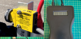
You cannot use just any optical sensor and claim success. I have tried a couple of low cost ones and they failed miserably at around 1600 rpm. I used a Banner Mini-Beam SM312LVMHS optical retroflective sensor which works great (stable, accurate, fast response time) and has no issue working in sunlight, unlike some infrared sensors I tested. Downside...$$$. It is about $200. I have sampled another brand of retroflective sensor for testing and it looks very promising, and cheap too... $20. More to come.
You can find preliminary schematics and some info at my Github site: https://github.com/Lycosaurus
I did a presentation to our EAA group a little over a year ago which you can find in the above Github site under the Vcheck_V0 folder.
As you can see, the documentation is a work in progress and I have been hampered by "life", including engine rebuild on my RV9A. I hope to find some time and motivation to fill in more blanks in the documentation.
I have no ambition to sell anything... just doing this for fun. You are welcome to use the information to build or design at your own risk and discretion. I claim no ownership.
I made a first quick (cheezy) video of my test setup uploaded to Youtube (see Vcheck_V0 folder). I have plans to post more videos of the Vcheck system as well as the successful field testing on my (victims) friends planes. Let me know what/if is of interest to you.
Vcheck_V0 is an Arduino Uno based device with crude point to point wiring. No pcb other than a perf-board. Vibration sensor is built upon the ADXL335 demo board, using a 3AA flashlight housing (slight modification and some epoxy).
Vcheck_V1 my productized and test-platform using an Arduino Nano, having two sensor inputs (I had plans for testing helicopters) encased in a professional sturdy housing with AA or 9V battery(-ies) that seems to be quite similar to one of the commercial analyzers. I also designed a PCB for the vibration sensor that gives access to 3 axes, temperature sensor (I was looking at possible a semi-permanent installation), and current drive buffering to drive the signals via a cable to the signal processing/display unit. Most of the features embedded in this design are not needed to perform basic vibration balancing functions.
Both the V0 and V1 versions run on any DC voltage from 3V to 16V.
The software performs quite well and makes use of Discrete Frequency Transform (a subset of FFT) and seems to be quite effective. The puny ADC of the Arduino is tapped to its max performance by sampling the next vibration level only when the previous data has been sampled and stored in the appropriate data bin (e.g. 120 bins of 3 degrees of propeller rotation... which can be changed by the user). No super high speed ADC needed.
As a system I have tested about 6 aircraft and brought the vibration levels from .4 ips to about .05 to .07 ips.
You cannot use just any optical sensor and claim success. I have tried a couple of low cost ones and they failed miserably at around 1600 rpm. I used a Banner Mini-Beam SM312LVMHS optical retroflective sensor which works great (stable, accurate, fast response time) and has no issue working in sunlight, unlike some infrared sensors I tested. Downside...$$$. It is about $200. I have sampled another brand of retroflective sensor for testing and it looks very promising, and cheap too... $20. More to come.
You can find preliminary schematics and some info at my Github site: https://github.com/Lycosaurus
I did a presentation to our EAA group a little over a year ago which you can find in the above Github site under the Vcheck_V0 folder.
As you can see, the documentation is a work in progress and I have been hampered by "life", including engine rebuild on my RV9A. I hope to find some time and motivation to fill in more blanks in the documentation.
I have no ambition to sell anything... just doing this for fun. You are welcome to use the information to build or design at your own risk and discretion. I claim no ownership.
I made a first quick (cheezy) video of my test setup uploaded to Youtube (see Vcheck_V0 folder). I have plans to post more videos of the Vcheck system as well as the successful field testing on my (victims) friends planes. Let me know what/if is of interest to you.
Attachments
RicoB
Well Known Member
Do you think that the MicrovibII is better than the dynavibe gx3?My MicroVib II reads IPS to 3 places, .001.
The sensor alone costs more than a complete DVib kit.
Microvibe is probably the state of the art and if I was doing MD500’s every day I’d have one.My MicroVib II reads IPS to 3 places, .001.
The sensor alone costs more than a complete DVib kit.
The Dynavibe is nice cuz it’s battery powered and you can take it with you easily and get data on any flight. Mine has the Strobex link which makes a huge reduction of time for getting an initial setup under .20 IPs quickly on a main rotor or tail rotor
The ONLY thing I don’t care for on microvibe is the algorithm and learning the system uses. I’d rather just have the raw data and stick to the chart.
I will say Microvibe on my Twin Commander 690a took already smooth turbines and took them to a silly level of smoothness.
On the 500 below .05 IPs, you can’t feel any dofference, so it’s really about saving part cost… over time.
No two ways about Microvibe being amazing .
Dynavibe for a piston prop though, is so simple you can be done before you even have the sensors and wires all run with the other systems. Just a great simple balancer to get you below .1 IPs and move on!
I've got a basic UI up on an esp32S3 supermini webserver. I'll order some parts and play around. Cheap fun.
Lycosaurus - I'll be asking for help!


Lycosaurus - I'll be asking for help!
Someone is enjoying their new found freedom from retirement!I've got a basic UI up on an esp32S3 supermini webserver. I'll order some parts and play around. Cheap fun.
Lycosaurus - I'll be asking for help!
")
we are in the middle of a blizzard here - gotta stop to go snow blow us and the neighbors now........Someone is enjoying their new found freedom from retirement!
walkman
Well Known Member
Pretty much concur with all of that, just wanted to get a handle on overall design. dual core is key for sureLooks like somebody has been talking to my friend Claude.
I think this is actually a remarkably good start. There are a few differences I had in mind.
- Processor - I'm starting with an RP2350 on a pico 2 w board. I considered an ESP32 and think it would be a good choice here. Ultimately, it really came down to me wanting to try out an RP2350. I just finished up a project with an ESP32 where I think the PIO of the RP2350 would have been very useful. I didn't want to go that route since I hadn't used one before. But for this project, an RP2350 with it's dual 150 MHz cores and DSP/floating point instructions sounds like a great fit.
- Accelerometer - As with your document, I plan on starting with an ADXL345. I do question if the precision and noise floor will be sufficient. I think the ADXL355 would be a better choice. But they are more expensive and I already have a few ADXL345s on hand. This should be an easy substitute later if I need to upgrade. (By my calculations, to read 0.05 IPS at 2200 RPM, the accelerometer will need to measure 0.03 g. Such a small signal will be difficult to read among all the other vibrations.)
- Optical Sensor - I don't think the TCRT5000 would be a good choice here. The datasheet mentions a 'DISTANCE RANGE FOR RELATIVE Iout > 20%' of only 0.2 to 15 mm. I'm pretty sure we'll want more range than that. I'm also looking at sensors with modulation filters for additional ambient light rejection.
- Display - I think I'm going to skip the display on the unit. Instead I'll go with a BLE connection and an app. Also will add an SD card for data logging.
- RTC - I plan on adding a real time clock just to be able to time stamp all logged data. This should make it easier to sync with my G3X log files for further analysis.
I did it with an Arduino Nano, then 2590Mega. Tried a lot of things including spectrum analysis -- FFT (DFT) with phase and amplitude. Takes a LOT of samples averaged to get rid of noise. Another thing is that to get down to 0.07 ips you need a sensitive accelerometer (or a lot of samples).
Started with the ADXL335. Then tried ADXL313.
https://homebuiltairplanes.com/threads/down-home-vibrometer.34747/ (posts #33, #39, #50, #58)

 homebuiltairplanes.com
homebuiltairplanes.com
homebuiltairplanes.com
Ended up mounting photo sensor and accelerometer permanently with data logging Arduino box in cockpit. Painted half of spinner back plate black, the other shiny alum.
Also tried the spreadsheet method (four runs, measuring max amplitude each time: 1) unbalanced, 2) add known weight at 0 degrees, 3) move the weight to 120 degrees, 4) move the weight to -120 degrees. Enter amplitudes in spreadsheet to get suggested weight. It's been a few years.) I'll be happy to dig up the details if you're interested.
Started with the ADXL335. Then tried ADXL313.
https://homebuiltairplanes.com/threads/down-home-vibrometer.34747/ (posts #33, #39, #50, #58)
Prop balancing
Having done 4 runs at 1,825 prop RPM, one with no weights, one with 11 grams at arbitrary 0-point, one at +113 deg and one at -113 deg, spreadsheet tells me to add 9 grams at 151 deg. The 11 gram test weight was added at the rim of the 13" spinner. But I need to add the actual weight on the...
homebuiltairplanes.com
Prop balancing - combining two weights
So I did new balancing runs with existing balance weight in place and now want to combine the two weights into one. What is the formula for that? Existing weight: 12 g @ 148 deg @ 5.9" radius. (10.5 g @ 148 @ 6.75" radius) New weight: 20 g @70 deg @ 6.75" radius. What is the combined weight...
homebuiltairplanes.com
Ended up mounting photo sensor and accelerometer permanently with data logging Arduino box in cockpit. Painted half of spinner back plate black, the other shiny alum.
Also tried the spreadsheet method (four runs, measuring max amplitude each time: 1) unbalanced, 2) add known weight at 0 degrees, 3) move the weight to 120 degrees, 4) move the weight to -120 degrees. Enter amplitudes in spreadsheet to get suggested weight. It's been a few years.) I'll be happy to dig up the details if you're interested.
Attachments
Last edited:
This is amazing. Exactly the sort of thing I was hoping (but not expecting) to find. For some reason github won't let me open any of your files. But I'll get that figured out, and am very interested to look at what you've done.Glad to see that other people are also interested in a DIY Propeller Balancer. I built two hardware versions based on ADXL335 vibration sensor and an Arduino based signal processing, including its built-in ADC.
Vcheck_V0 is an Arduino Uno based device with crude point to point wiring. No pcb other than a perf-board. Vibration sensor is built upon the ADXL335 demo board, using a 3AA flashlight housing (slight modification and some epoxy).
Vcheck_V1 my productized and test-platform using an Arduino Nano, having two sensor inputs (I had plans for testing helicopters) encased in a professional sturdy housing with AA or 9V battery(-ies) that seems to be quite similar to one of the commercial analyzers. I also designed a PCB for the vibration sensor that gives access to 3 axes, temperature sensor (I was looking at possible a semi-permanent installation), and current drive buffering to drive the signals via a cable to the signal processing/display unit. Most of the features embedded in this design are not needed to perform basic vibration balancing functions.
Both the V0 and V1 versions run on any DC voltage from 3V to 16V.
The software performs quite well and makes use of Discrete Frequency Transform (a subset of FFT) and seems to be quite effective. The puny ADC of the Arduino is tapped to its max performance by sampling the next vibration level only when the previous data has been sampled and stored in the appropriate data bin (e.g. 120 bins of 3 degrees of propeller rotation... which can be changed by the user). No super high speed ADC needed.
As a system I have tested about 6 aircraft and brought the vibration levels from .4 ips to about .05 to .07 ips.
For my optical sensor I'm currently using an IR LED and receiver that I already had. So far it's been working on my test setup. (Cutoff wheel with a piece of reflective tape mounted in a cordless drill.) But that only goes up to around 1300 RPM. Based off your warning I'll do some additional testing. Think I'll start with adding some additional strips of tape to simulate a higher RPM. Might also try to characterize the response of the IR receiver by quickly pulsing the LED while monitoring the input and output on the oscilloscope. Figure out the minimum pulse width needed to trigger and if there's any significant turn on/off delays.You cannot use just any optical sensor and claim success. I have tried a couple of low cost ones and they failed miserably at around 1600 rpm. I used a Banner Mini-Beam SM312LVMHS optical retroflective sensor which works great (stable, accurate, fast response time) and has no issue working in sunlight, unlike some infrared sensors I tested. Downside...$$$. It is about $200. I have sampled another brand of retroflective sensor for testing and it looks very promising, and cheap too... $20. More to come.
Same here. In the spirit of experimental aviation, I'm doing this solely for my own education and recreation. If others are interested, I'll gladly share my results.I have no ambition to sell anything... just doing this for fun. You are welcome to use the information to build or design at your own risk and discretion. I claim no ownership.
I should mention that I mounted the TCRT5000 optical sensor in a 1/2" CPVC pipe and it's about 1/8" from the spinner back plate. Very easy to ruin the signal with sunlight as you're climbing out.
I think model airplanes with props turning 5,000 to 15,000 RPM have it easier because signal level in creases with RPM, as mentioned.
Having a gearbox (as with Rotax) complicates matters. You have to separate engine vibration from prop vibration. If you're lucky the gearbox ration is a non-integer number making it easier to filter out (engine RPM not a harmonic of prop RPM).
Thanks for the post. It's great to see that others have done this successfully. I tried looking at your posts over at homebuiltairplanes. Unfortunately, I can only view the first three posts in a thread. Every post after that is obscured and not viewable.I did it with an Arduino Nano, then 2590Mega. Tried a lot of things including spectrum analysis -- FFT (DFT) with phase and amplitude. Takes a LOT of samples averaged to get rid of noise. Another thing is that to get down to 0.07 ips you need a sensitive accelerometer (or a lot of samples).
Started with the ADXL335. Then tried ADXL313.
https://homebuiltairplanes.com/threads/down-home-vibrometer.34747/ (posts #33, #39, #50, #58)
Prop balancing
Having done 4 runs at 1,825 prop RPM, one with no weights, one with 11 grams at arbitrary 0-point, one at +113 deg and one at -113 deg, spreadsheet tells me to add 9 grams at 151 deg. The 11 gram test weight was added at the rim of the 13" spinner. But I need to add the actual weight on the...Prop balancing - combining two weights
So I did new balancing runs with existing balance weight in place and now want to combine the two weights into one. What is the formula for that? Existing weight: 12 g @ 148 deg @ 5.9" radius. (10.5 g @ 148 @ 6.75" radius) New weight: 20 g @70 deg @ 6.75" radius. What is the combined weight...
Ended up mounting photo sensor and accelerometer permanently with data logging Arduino box in cockpit. Painted half of spinner back plate black, the other shiny alum.
Also tried the spreadsheet method (four runs, measuring max amplitude each time: 1) unbalanced, 2) add known weight at 0 degrees, 3) move the weight to 120 degrees, 4) move the weight to -120 degrees. Enter amplitudes in spreadsheet to get suggested weight. It's been a few years.) I'll be happy to dig up the details if you're interested.

As my username would suggest, I've got a Rotax 912is. I believe this has a 2.43:1 gearbox ratio. As you mentioned, this ratio should make it easier to separate the engine from the prop vibrations. Eventually I plan to report both. Although the engine will have to be vibration magnitude only, as I won't have a reference for degrees of rotation.I should mention that I mounted the TCRT5000 optical sensor in a 1/2" CPVC pipe and it's about 1/8" from the spinner back plate. Very easy to ruin the signal with sunlight as you're climbing out.
I think model airplanes with props turning 5,000 to 15,000 RPM have it easier because signal level in creases with RPM, as mentioned.
Having a gearbox (as with Rotax) complicates matters. You have to separate engine vibration from prop vibration. If you're lucky the gearbox ration is a non-integer number making it easier to filter out (engine RPM not a harmonic of prop RPM).
Sorry, wasn't aware that anybody can't view all of threads there. Free to sign up. Anyway, I guess I can summarize some lessons learned here.
Converting acceleration to ips:


where acceleration is in Gs, velocity in ips and Frequency is cycles per minute (RPM).
If running prop at 1000 RPM and want to detect 0.07 ips or less, we're looking for 0.015 Gs. If using the ADXL335, that has a sensitivity of 300 mV/G, that's 4.5mV!
Doubling the RPM to 2,000 we're looking to get the vibration below 9 mV from the ADXL335.
As you can see we're working close to the 4.9mV/bit resolution of a 10-bit A/D converter @5V.
If feeding the ADXL335 signal to an Arduino Nano or Mega (has a 0 to 5V range and 4.9mV resolution) I'll probably first have to amplify the signal 100 to 200 times to get a reasonable resolution.
Trying to understand FFT (DFT):
See attached FFT tutorial.
I think the light bulb finally came on:
Sample two channels simultaneously:
1) trigger signal
and
2) accelerometer signal.
Then do FFT on both sample sets.
Note the frequency "bin" with the highest accelerometer peak (should also be RPM/60)
Read the phase from the trigger channel same bin.
Most stable phase results if sampling starts on trigger signal.
Summary of last posts:
"Seems the prop balancers out there brags about bringing it below 0.07 ips.
So what I already have (ADXL335 with 20x, 60x and 100x amplification) should be adequate. Still, it will be interesting to see what the ADXL313 can do. Output data rate sets bandwidth:
Output Data Rate (Hz) - Bandwidth (Hz) Rate
400 - 200
200 - 100
100 - 50
50 - 25
25 - 12.5
12.5 - 6.25
50Hz (3,000RPM) should be quite adequate for prop balancing.
Wanted to post an update one using the ADXL335 all-digital accelerometer because it may be a while before I get to continue testing.
I decided to try it out because I had already purchased it and because I should be able to get fairly accurate absolute acceleration values. (One LSB is 1/1024 Gs.)
Prop is already pretty well balanced by adding 1/4" carbide rods in heavy side of hub and painting the light blade black on backside, so this is mainly curiosity.
So the objective here is to measure absolute prop acceleration.
Some points I encountered:
Even though the ADXL335 is capable of 1,600 samples/second, the digital SPI or I2C interfaces limits how fast you can get the data into for example my Arduino Mega 2560.
The built-in bandwidths (low pass filter) fixed to 1/2 of sample rate may not be ideal.
During actual ground runs I saw what I thought were much too high values. After some research I found out that one needs to divide the values gotten after doing FFT (DFT) by number-of-samples/2 to get correct (peak acceleration) values!
I still don't know if the ips vibration that, for example Dynavibe reports, is peak, peak-peak or RMS.
I tried different algorithms to determine prop vibration. I've given up on the 2-channel FFT amplitude and phase method. It may work with an electrical motor but not with impossibly noisy phase signal on a combustion engine and prop. Instead I've gone to the 4-run test-weight spreadsheet method to determine weight and angle.
My latest algorithm is to measure prop period (RPM) by trigger signals, and then take 32 samples (the ADXL335 set to 1600 samples/sec but reading the data at 1/32 prop rotation period intervals) through one full prop revolution. That can be repeated (for example 1, 2, 4, 8, 16, 32 or 64 times) and averaged to get rid of noise. The prop vibration amplitude should be found in the lowest frequency (non-DC) FFT "bin". The frequency of that bin of course is prop-RPM/ 60.
I decided on that algorithm after doing some simulations. Unless you can set the sample rate to a multiple of the prop RPM or frequency (not possible with the ADXL335), the adjacent FFT frequency or spectrum "bins" will get part of the amplitude, unless you can hit and maintain the exact RPM for that sample rate. In other words, at a fixed sample rate, as you vary RPM, looking at the FFT spectrum, you'll see one frequency peak and adjacent frequencies being zero and then grow. I was not able to calculate accurate values by pro-rating the adjacent bin amplitude values by RPM frequency ratio to bin frequencies (by how far the measured frequency is from bin frequencies).
Another method I need to look into is quadrature. If a signal frequency (RPM) is known, one can apparently multiply samples of that signal with exponential or trig functions and obtain amplitude of the sampled signal? Probably the same that's done in FFT/DFT but for a one-channel FFT? Question will be how stable is the rotational speed (frequency or RPM) of a prop through one or more sampled rotations?
Will be interesting to see results from actual flight data collection runs."
Maybe I was limited by the speed of the Arduino Mega and may be able to get better results using an ESP32 and the "Step 3: Extracting the 1× Vibration Vector" in the ESP32_Propeller_Balancer_Design.pdf in post #11 above.
Have fun and by all means posts your experience and results.
Finn
EDIT: Of course the above reveals my complete ignorance on how FFT or DFT is actually done. I simply included an Arduino FFT library in my code.
Converting acceleration to ips:
where acceleration is in Gs, velocity in ips and Frequency is cycles per minute (RPM).
If running prop at 1000 RPM and want to detect 0.07 ips or less, we're looking for 0.015 Gs. If using the ADXL335, that has a sensitivity of 300 mV/G, that's 4.5mV!
Doubling the RPM to 2,000 we're looking to get the vibration below 9 mV from the ADXL335.
As you can see we're working close to the 4.9mV/bit resolution of a 10-bit A/D converter @5V.
If feeding the ADXL335 signal to an Arduino Nano or Mega (has a 0 to 5V range and 4.9mV resolution) I'll probably first have to amplify the signal 100 to 200 times to get a reasonable resolution.
Trying to understand FFT (DFT):
See attached FFT tutorial.
I think the light bulb finally came on:
Sample two channels simultaneously:
1) trigger signal
and
2) accelerometer signal.
Then do FFT on both sample sets.
Note the frequency "bin" with the highest accelerometer peak (should also be RPM/60)
Read the phase from the trigger channel same bin.
Most stable phase results if sampling starts on trigger signal.
Summary of last posts:
"Seems the prop balancers out there brags about bringing it below 0.07 ips.
So what I already have (ADXL335 with 20x, 60x and 100x amplification) should be adequate. Still, it will be interesting to see what the ADXL313 can do. Output data rate sets bandwidth:
Output Data Rate (Hz) - Bandwidth (Hz) Rate
400 - 200
200 - 100
100 - 50
50 - 25
25 - 12.5
12.5 - 6.25
50Hz (3,000RPM) should be quite adequate for prop balancing.
Wanted to post an update one using the ADXL335 all-digital accelerometer because it may be a while before I get to continue testing.
I decided to try it out because I had already purchased it and because I should be able to get fairly accurate absolute acceleration values. (One LSB is 1/1024 Gs.)
Prop is already pretty well balanced by adding 1/4" carbide rods in heavy side of hub and painting the light blade black on backside, so this is mainly curiosity.
So the objective here is to measure absolute prop acceleration.
Some points I encountered:
Even though the ADXL335 is capable of 1,600 samples/second, the digital SPI or I2C interfaces limits how fast you can get the data into for example my Arduino Mega 2560.
The built-in bandwidths (low pass filter) fixed to 1/2 of sample rate may not be ideal.
During actual ground runs I saw what I thought were much too high values. After some research I found out that one needs to divide the values gotten after doing FFT (DFT) by number-of-samples/2 to get correct (peak acceleration) values!
I still don't know if the ips vibration that, for example Dynavibe reports, is peak, peak-peak or RMS.
I tried different algorithms to determine prop vibration. I've given up on the 2-channel FFT amplitude and phase method. It may work with an electrical motor but not with impossibly noisy phase signal on a combustion engine and prop. Instead I've gone to the 4-run test-weight spreadsheet method to determine weight and angle.
My latest algorithm is to measure prop period (RPM) by trigger signals, and then take 32 samples (the ADXL335 set to 1600 samples/sec but reading the data at 1/32 prop rotation period intervals) through one full prop revolution. That can be repeated (for example 1, 2, 4, 8, 16, 32 or 64 times) and averaged to get rid of noise. The prop vibration amplitude should be found in the lowest frequency (non-DC) FFT "bin". The frequency of that bin of course is prop-RPM/ 60.
I decided on that algorithm after doing some simulations. Unless you can set the sample rate to a multiple of the prop RPM or frequency (not possible with the ADXL335), the adjacent FFT frequency or spectrum "bins" will get part of the amplitude, unless you can hit and maintain the exact RPM for that sample rate. In other words, at a fixed sample rate, as you vary RPM, looking at the FFT spectrum, you'll see one frequency peak and adjacent frequencies being zero and then grow. I was not able to calculate accurate values by pro-rating the adjacent bin amplitude values by RPM frequency ratio to bin frequencies (by how far the measured frequency is from bin frequencies).
Another method I need to look into is quadrature. If a signal frequency (RPM) is known, one can apparently multiply samples of that signal with exponential or trig functions and obtain amplitude of the sampled signal? Probably the same that's done in FFT/DFT but for a one-channel FFT? Question will be how stable is the rotational speed (frequency or RPM) of a prop through one or more sampled rotations?
Will be interesting to see results from actual flight data collection runs."
Maybe I was limited by the speed of the Arduino Mega and may be able to get better results using an ESP32 and the "Step 3: Extracting the 1× Vibration Vector" in the ESP32_Propeller_Balancer_Design.pdf in post #11 above.
Have fun and by all means posts your experience and results.
Finn
EDIT: Of course the above reveals my complete ignorance on how FFT or DFT is actually done. I simply included an Arduino FFT library in my code.
Attachments
Last edited:
Rereading posts I feel I should emphasize this: there is a huge difference between successfully doing it on a prop driven by an electrical motor (bench test and model airplane) and on a combustion engine on an airplane (even more so via a gearbox). Don't want to discourage you but just be aware it might not be as simple as it's been made out to be. But then again, it's all for fun, education and experimentation.
The digital ADXL345 has been mentioned a few times but let me point out that it only has a resolution of 4 mGs per bit (LSB). At 2,000RPM that's only 0.07ips.
At least the digital output ADXL313 has "fixed 1024 LSB/g sensitivity for any g range" or about 0.001G/LSB or 0.002 ips per LSB at 2,000 RPM. Please correct me if my math is wrong. To get higher accuracy you'll need an accelerometer with analog output followed by op-amp to amplify the signal before it goes to the CPU 's A/D converter, but now you have a calibration issue: amplification factor correct at all relevant frequencies and noise?
The way I read the datasheet for the ADXL313 is that it has ranges of +/-0.5g, +/-1g, +/-2g, and +/-4g, and 13-bit resolution. Thus, on the +/-0.5g range, with 10-bit resolution, the resolution in g is 0.5g/512, or about 0.00098g. On the +/-1g range, sliding the 10-bit window on the 13-bit number one bit to the left, the resolution in g is 1g/512, or about 0.00195g. On the 4g range, the resolution is about 0.0078g. (10 bit unsigned resolution is 1 part in 1024; for signed data, it's -512 to +511, and we're dealing with +/-0.5, +/-1, etc.).At least the digital output ADXL313 has "fixed 1024 LSB/g sensitivity for any g range" or about 0.001G/LSB or 0.002 ips per LSB at 2,000 RPM. Please correct me if my math is wrong.
I don't think the +/- 0.5g range is useful, because we're conducting these tests on Earth, so we are already subject to 1g acceleration toward the center of the planet. Any wiggle on the flywheel is probably swamped by that constant 1g, and if not, I might be running away from the rotating machinery.
Another question is regarding how to express frequency. Is it frequency in Hz (RPM/60), or is it in radians per second (multiply Hz by 2*pi)? I think it's in radians per unit time, i.e., angular frequency.
So for 2000 RPM, or 33.33 Hz, or 209.44 radians/second, using the relationship peak acceleration in inches/sec^2 = 386.1 * peak acceleration in g's, 1g peak acceleration in inches/sec^2 = 0.753 in/s^2. (1g = 9.80665 m/s² and 1 inch = 0.0254 m, 9.80665/0.0254 ~= 386.1 in/s²) The peak velocity is the peak acceleration divided by the angular frequency, or 0.753/209.44, or 0.00359 in/s. So I think the resolution of the ADXL313 on the 1g scale is a peak velocity of 0.00359 ips.
But... if you enable full resolution, you get 11 bits for +/- 1g, so the resolution on the 1g scale is about 0.0018 ips. More better, and pretty close to the stated 0.002 ips.
But that's just my opinion...
And I tend to agree with FinnFlyer's post #29. Some experiments are more risky than others.
Things could get really interesting if you could mount two accelerometers 90 degrees apart, and synchronize them in terms of their sampling time, and thus do quadrature (sine and cosine) sampling. You could measure both the magnitude and the phase of the vibration pretty quickly, once you stabilize the RPM.
Last edited:
I'll gladly take any advice from someone who has tried to do this before. I've thought from the beginning, the difficult part will be extracting the vibration I'm interested in out from among the other noise and vibrations. Fortunately, since I'm doing this for my own education and entertainment, it is okay if I never get it to work. Either way I am learning a lot.Rereading posts I feel I should emphasize this: there is a huge difference between successfully doing it on a prop driven by an electrical motor (bench test and model airplane) and on a combustion engine on an airplane (even more so via a gearbox). Don't want to discourage you but just be aware it might not be as simple as it's been made out to be. But then again, it's all for fun, education and experimentation.
I didn't check your math here, but I agree the ADXL345 may be a marginal choice. My first choice was the ADXL355. I think it's a much better fit for this application. However, it's more expensive and I already had a few ADXL345 on hand. So I was going to start testing and perform code validation with those. If I need to upgrade later, it should be easy to change.The digital ADXL345 has been mentioned a few times but let me point out that it only has a resolution of 4 mGs per bit (LSB). At 2,000RPM that's only 0.07ips.
At least the digital output ADXL313 has "fixed 1024 LSB/g sensitivity for any g range" or about 0.001G/LSB or 0.002 ips per LSB at 2,000 RPM. Please correct me if my math is wrong. To get higher accuracy you'll need an accelerometer with analog output followed by op-amp to amplify the signal before it goes to the CPU 's A/D converter, but now you have a calibration issue: amplification factor correct at all relevant frequencies and noise?
I'm new to this, so my thoughts don't mean much. But, to me, it comes down to what you're referring to. If you're referring to a rotational vibration, then amount of rotation per unit of time makes sense. However, if you're measuring this rotational vibration along a given axis... then that would be measured in Hertz. (Although ultimately I have no preference and probably use the wrong terms at least half the time anyways.)Another question is regarding how to express frequency. Is it frequency in Hz (RPM/60), or is it in radians per second (multiply Hz by 2*pi)? I think it's in radians per unit time, i.e., angular frequency.
Funny you should mention this... The ADXL345 (and ADXL355) is a three axis accelerometer. Less than an hour before you made this comment, I made the decision to rotate the accelerometer 90 degrees and implemented the code changes to get accelerometer readings on both the X and Y. (On the ADXL345, the Z axis is noisier than X or Y. If I was using two axis simultaneously, I wanted their performance to match. By rotating 90 degrees the X axis is now vertical (up/down) and the Y axis is horizontal (left/right))Things could get really interesting if you could mount two accelerometers 90 degrees apart, and synchronize them in terms of their sampling time, and thus do quadrature (sine and cosine) sampling. You could measure both the magnitude and the phase of the vibration pretty quickly, once you stabilize the RPM.
Didn't know about the ADXL355. $68 but impressive 1000x better resolution!
Of course we could easily get carried away here. Someone mentioned that a bug splashed on a prop blade could easily throw off a prop balanced to 0.07 ips.
Still would like to know if Dynavibe shows peak, peak-peak, average or RMS ips.
Of course we could easily get carried away here. Someone mentioned that a bug splashed on a prop blade could easily throw off a prop balanced to 0.07 ips.
Still would like to know if Dynavibe shows peak, peak-peak, average or RMS ips.
Yep. It's in another class, in both price and performance.Didn't know about the ADXL355. $68 but impressive 1000x better resolution!
Most references I've seen refer to peak IPS. For example, here's an excerpt from "ACES SystemsGuide to Propeller Balancing".Still would like to know if Dynavibe shows peak, peak-peak, average or RMS ips.

I couldn't find too much from Dynavibe specifically. But here's a reference from their DynaVibe GX manual that indicates they too likely use peak IPS.

I do wonder how useful horizontal acceleration will be. Most balancers I've looked at specifically measure acceleration vertically. I'm guessing this is because vibration from the horizontally moving cylinders would typically be indistinguishable from prop vibrations. However, since the Rotax has a gear reduction, the prop and engine don't rotate at the same frequency. So theoretically, after the accelerometer data is collected and converted to a frequency domain it should be possible to distinguish between the two. I want to collect some actual data and do some analysis on it. See if the results provide actually useful information from horizontal acceleration.Things could get really interesting if you could mount two accelerometers 90 degrees apart, and synchronize them in terms of their sampling time, and thus do quadrature (sine and cosine) sampling. You could measure both the magnitude and the phase of the vibration pretty quickly, once you stabilize the RPM.
As you probably know, with simultaneous measurements of acceleration in two orthogonal directions, you can do a complex (real and imaginary parts) FFT, not just a real (single-axis) FFT. From the complex numbers in each frequency bin of the FFT output you can derive magnitude ( sqrt(Re^2 + Im^2) ) and phase ( atan2(Im, Re) ) of the acceleration at that frequency.I do wonder how useful horizontal acceleration will be. Most balancers I've looked at specifically measure acceleration vertically. I'm guessing this is because vibration from the horizontally moving cylinders would typically be indistinguishable from prop vibrations. However, since the Rotax has a gear reduction, the prop and engine don't rotate at the same frequency. So theoretically, after the accelerometer data is collected and converted to a frequency domain it should be possible to distinguish between the two. I want to collect some actual data and do some analysis on it. See if the results provide actually useful information from horizontal acceleration.
I have a System32 ignition system so I am going to try to get a timing signal from that (it has multiple crank position signals). Has anyone considered putting a sensor on a sparkplug wire for a timing signal? It would sense the high voltage going through the wire without contact. That seems easier than an optical sensor, particularly for permanently mounted projects.
Try a Hall effect sensor or inductive clamp to sense the current through the plug wire. Basically the same idea as the trigger for a timing light. The current will be fairly low, on the order of 100-200 milliamps peak, so the sensor must be more sensitive than the ones used on alternator B leads. The peak current happens for a very brief time as the spark gap ionizes, so the frequency response of the sensor must be high. And depending on what type of ignition system you have, the spark pulse may vary in phase with respect to TDC. Consequently (circling back to the thread topic), spark timing isn't very useful for triggering an accelerometer for prop balancing, unless you know and can compensate for the spark advance.I have a System32 ignition system so I am going to try to get a timing signal from that (it has multiple crank position signals). Has anyone considered putting a sensor on a sparkplug wire for a timing signal? It would sense the high voltage going through the wire without contact. That seems easier than an optical sensor, particularly for permanently mounted projects.
I've ran across one project where they are doing just that: https://github.com/peterashwoodsmith/vcheck.I have a System32 ignition system so I am going to try to get a timing signal from that (it has multiple crank position signals). Has anyone considered putting a sensor on a sparkplug wire for a timing signal? It would sense the high voltage going through the wire without contact. That seems easier than an optical sensor, particularly for permanently mounted projects.
Here's a video of them doing some bench testing.
As for me, I am using a Rotax with a 2.43:1 gearbox. So even if I were to get engine position information, that won't help with prop location.
the ACES balancer appears to have an older version of this STI accelerometer with the integrated cable https://www.stiweb.com/CMCP1100_Low_Cost_Industrial_Accelerometer_p/cmcp1100.htm . they measure down to single digit hundredth of an IPShere's an excerpt from "ACES SystemsGuide to Propeller Balancing".
I could not find the old part number but it looks visually the same as CMCP1100. must be mounted vertically..
He's using a spark sensor as a RPM trigger. However, I don't see where he's compensating for spark being every 720° in the code.I've ran across one project where they are doing just that: https://github.com/peterashwoodsmith/vcheck.
Here's a video of them doing some bench testing.I'm assuming for this to work they must have a system with a fixed spark advance.
As for me, I am using a Rotax with a 2.43:1 gearbox. So even if I were to get engine position information, that won't help with prop location.
You could replace that trigger with any other tach signal like an optical tach or a hall effect sensor or whatever. Honestly I wouldn't bother using spark as a tach. Too many human variables (even if you lock the advance) vs placing a dot on a blade and using an optical sensor.
The amount of lag from the accelerometer is interesting. He's got 70° at 3600 RPM and 5° at 1700.
Timing Signal:
I contacted Robert at FlyEFII and per his advice, I'm going to look at the RPM signal. It's a two pulse per rev signal, which should work as we just need a signal that happens at the same place on each engine revolution. The hall effect sensors mentioned above would work, too. I'm just trying to use what's already available.
-Jason
Here's another video that mentions a couple of optical sensors in the video description.As for me, I am using a Rotax with a 2.43:1 gearbox. So even if I were to get engine position information, that won't help with prop location.
Looking at the datasheet for the QRD1114, its max sensitivity (max collector current) is with a distance between 20 and 30 mils. That's 0.025" or 0.6mm!Here's another video that mentions a couple of optical sensors in the video description.
Didn't find that spec for the ITR20001/T.
Just something to be aware of in addition to shielding from ambient light or heat sources.
That's probably why Dynavibe and others are using the more expensive laser position sensors.
As I mentioned, I have my photo LED/transistor in a 1/2 CPVC tube to shield from ambient light and very close (<1/8") from the spinner back plate which is 1/2 painted black to produce a square wave. (Actually added a piece of thin reflective tape just before the black to get an sharper start edge.)
Yeah, I noticed that too. Better alternatives ($$$) would be sensors like the Omron E3Z‑R61 / R62 or the Keyence PZ‑V/M Series. Or do like you did.Looking at the datasheet for the QRD1114, its max sensitivity (max collector current) is with a distance between 20 and 30 mils. That's 0.025" or 0.6mm!
Didn't find that spec for the ITR20001/T.
Just something to be aware of in addition to shielding from ambient light or heat sources.
That's probably why Dynavibe and others are using the more expensive laser position sensors.
As I mentioned, I have my photo LED/transistor in a 1/2 CPVC tube to shield from ambient light and very close (<1/8") from the spinner back plate which is 1/2 painted black to produce a square wave. (Actually added a piece of thin reflective tape just before the black to get an sharper start edge.)
I'm currently testing a Vishay TSSP77038. It's an "IR Sensor Module for Reflective Sensor, Light Barrier, and Fast Proximity Applications". The data sheet claims it will work in presence detection applications up to 2 meters. Where I plan on mounting it, it will only be 2-3 inches behind the spinner. One of the nice features of it is a bandpass filter in the reception circuitry. It doesn't trigger off of steady light. It needs to see a 940 nm light modulated at 38 kHz. This greatly improves it's ambient light rejection.
One down side to this sensor is that it has a fairly wide field of view. This obviously is not ideal for this application. So I plan on 3d printing a housing around the receiver with a small aperture to limit it's view.
One down side to this sensor is that it has a fairly wide field of view. This obviously is not ideal for this application. So I plan on 3d printing a housing around the receiver with a small aperture to limit it's view.
So far I've been taking the advice from others on which accelerometer to use.
@rv12is, how did you arrive at the ADXL355?
Trying Analog Devices' selection table for Accelerometers it doesn't have a column for sensitivity nor resolution.
Did you read through all their datasheets? I'm lazy and if you've already done that and found the ADXL355 to be the highest resolution (20 bits), or most sensitive, I won't have to go through that exercise.
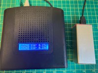
Here's the hardware I've been working with.

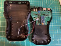
It's got a Pi Pico 2 W (RP2350) microcontroller, ADXL345 accelerometer, DS3231 real time clock, TSSP77038 IR receiver, IR333-A IR Led, and a 1 gigabyte SD card. I've almost got the firmware and app to a point where it's ready to mount to the plane and log some accelerometer data. The problem is, there's no way I'm bolting hardware like this to an airplane engine. It needs to be repackaged.
I'm sure I'll hate myself later for making this so tight and not leaving much room to run wires. But here's what my current proposed packaging looks like.


The 3d printed gray angle piece is 3.75" long and I'll fabricate that out of 1" aluminum angle. The black plastic housing will be reprinted in black ASA. As will the currently green IR LED/receiver housing. The accelerometer board will have washers under it for spacing and be secured by four screws directly into the aluminum. The bottom part of the case is secured with four screws from under the angle. The remaining boards slide into place and are secured by installing the case top with four screws. When installed, the sd card sticks out just enough to grab it. For now, power is supplied through a micro usb connector. I'm pretty sure that's about as compact as I can get it without a custom PCB. That's for the next revision. After I verify if this will actually work.
This will be bolted to the gearbox using the two holes circled in the image below. That should place it behind the cowling, and just far enough inside to have a clear view of the backside of the spinner.


Based off what I've been reading, accelerometer placement and mounting is super critical. While I think my approach is pretty solid, if anyone has feedback on how to improve it that would be appreciated.
It's got a Pi Pico 2 W (RP2350) microcontroller, ADXL345 accelerometer, DS3231 real time clock, TSSP77038 IR receiver, IR333-A IR Led, and a 1 gigabyte SD card. I've almost got the firmware and app to a point where it's ready to mount to the plane and log some accelerometer data. The problem is, there's no way I'm bolting hardware like this to an airplane engine. It needs to be repackaged.
I'm sure I'll hate myself later for making this so tight and not leaving much room to run wires. But here's what my current proposed packaging looks like.
The 3d printed gray angle piece is 3.75" long and I'll fabricate that out of 1" aluminum angle. The black plastic housing will be reprinted in black ASA. As will the currently green IR LED/receiver housing. The accelerometer board will have washers under it for spacing and be secured by four screws directly into the aluminum. The bottom part of the case is secured with four screws from under the angle. The remaining boards slide into place and are secured by installing the case top with four screws. When installed, the sd card sticks out just enough to grab it. For now, power is supplied through a micro usb connector. I'm pretty sure that's about as compact as I can get it without a custom PCB. That's for the next revision. After I verify if this will actually work.
This will be bolted to the gearbox using the two holes circled in the image below. That should place it behind the cowling, and just far enough inside to have a clear view of the backside of the spinner.
Based off what I've been reading, accelerometer placement and mounting is super critical. While I think my approach is pretty solid, if anyone has feedback on how to improve it that would be appreciated.
I did not do an exhaustive search. There may be better options out there. I just started with the 345. When I began to question if it was going to be good enough, I searched for alternatives. Looked at a few options and found the 355. I didn't look much after that.So far I've been taking the advice from others on which accelerometer to use.
@rv12is, how did you arrive at the ADXL355?
Trying Analog Devices' selection table for Accelerometers it doesn't have a column for sensitivity nor resolution.
Did you read through all their datasheets? I'm lazy and if you've already done that and found the ADXL355 to be the highest resolution (20 bits), or most sensitive, I won't have to go through that exercise.
I've attached a summary from my friend Claude. An excerpt from this document is shown below.

Attachments
