Both ideas make total sense. Thank you!Marc, You will note that the fifth rivet back on the top of each nose rib has it's tail blocked by the stringer making it difficult to get a bucking bar in there. So, we removed the stringer clecos and slide the stringer out one end of the wing which gave us a clear shot at the rivet tail. Then we set the one rivet on each nose rib, slide the stringer back in place, clecoed it and pressed on.

Van's Air Force
You are using an out of date browser. It may not display this or other websites correctly.
You should upgrade or use an alternative browser.
You should upgrade or use an alternative browser.
RV-15 #150046 (Wing Kit)
- Thread starter MCA
- Start date

wiktor256
I'm New Here
This bothers me as well. I am thinking about riveting the tube to the middle rib.Additionally, some Dowsil 737 silicone (Proseal would work too) was used on the middle rib to minimize the rib vibrating on the tube. I'm not sure why this metal to metal unsecured contact is OK.
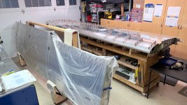
Here's a few pics of the stands used to hold the wing (and the ailerons and flaps). They were made out of spare wood from the shipping crates, and the foam used in the large crate. They should be made as wide as your table, and after early versions often slipped off the table, the side supports were added to keep the stands secure on the table.


They bend and conform to the wing.
They bend and conform to the wing.
Here's a few pics of the stands used to hold the wing (and the ailerons and flaps). They were made out of spare wood from the shipping crates, and the foam used in the large crate. They should be made as wide as your table, and after early versions often slipped off the table, the side supports were added to keep the stands secure on the table.
View attachment 116281
View attachment 116282
They bend and conform to the wing.
Nice! The foam will come in handy. How many supports are you putting under the wing?
I have two different tables and so one support on each table keeps everything stable.Nice! The foam will come in handy. How many supports are you putting under the wing?
Was sick for a few days but finally managed to get the LEFT wing cleco'd and riveted. Recall that all the rivets forward of the main spar are solid flush rivets (426AD4-4). The process below is for that setup. (which is NON STANDARD)

Thanks for the great input from others and the WIKI regarding solid rivets. I used a 3x gun, tungsten bucking bar, and pressure set to 40 PSI. It was no problem to buck the larger rivets and there's no need to use softer rivets.
However, with all the riveting completed, there's a pretty good cross section of quality of rivets as well as some unwanted dents in the sheet metal. I found it to be a tricky setup and many times your body, arms, etc. are not in ideal positions. An inspection mirror and light is a must.
I followed the sequence of events as laid out in the KAIs. If it called for a pulled rivet, then we pulled rivets. If it called to rivet the nose skin, we riveted the 426 rivets.
Here's the prep:
1. Do not install anything on or in the nose ribs until the riveting is done. That means plastic clips, pitot/AOA hose, snap bushings, landing light bracket and 1/4 rib, and wiring harness. You'll want as much room as possible in there. Most of this went in easily later on, but a ferw clips were tricky. Think through the sequence needed to re-install these parts, particularly around and behind the landing light bracket.
2. Remove the two stringers in the nose section, and only rivet those in after the other riveting is done. As mentioned above, it worked great to slide them out and they slid right back in later. (keep in mind the two short stringers are different, and only one works correctly per side)
3. Dimple the nose ribs, landing light bracket, 1/4 rib
4. Dimple the LE (nose) skins. Careful at the inboard and outboard edges as there are holes for fairings that don't get dimpled. I use a Sharpie to circle the holes that need a dimple.
The hardest part is the inboard set of rivets on the outboard double rivet edge sections. It's difficult to get to and inspect. A second SKILLED person would be very helpful.
You'll really have to decide if you want perfect rivets, or if you want to fly in a reasonable future time. Most turned out acceptable, a few were drilled out, and I decided to leave a few uglies in there. There's always a cost to drilling rivets, so it is a trade.
This would be super easy (SuperEasy ) if Van's provided guidance that allowed flush pull rivets. Too late for me, but hopefully they can do that soon.

Top skin:

Bottom skin:


The AN5 bolt on the strut attach fitting was a super tight fit through the spar. You may want to check that prior to assembly.

Next: secure wiring and install the fairing on the aft side of the wing.
Additionally, the connector bracket was slightly modified to use a clip (I bought extra) which provies an elegant way to route the fuel sender wiring and ground wire to the main connector. Van's has not specified how they plan to incorporate the fuel sender wiring, but since the CiES senders use different wiring I am using the main connector for all electrical (fuel senders and puddle light power).

Thanks for the great input from others and the WIKI regarding solid rivets. I used a 3x gun, tungsten bucking bar, and pressure set to 40 PSI. It was no problem to buck the larger rivets and there's no need to use softer rivets.
However, with all the riveting completed, there's a pretty good cross section of quality of rivets as well as some unwanted dents in the sheet metal. I found it to be a tricky setup and many times your body, arms, etc. are not in ideal positions. An inspection mirror and light is a must.
I followed the sequence of events as laid out in the KAIs. If it called for a pulled rivet, then we pulled rivets. If it called to rivet the nose skin, we riveted the 426 rivets.
Here's the prep:
1. Do not install anything on or in the nose ribs until the riveting is done. That means plastic clips, pitot/AOA hose, snap bushings, landing light bracket and 1/4 rib, and wiring harness. You'll want as much room as possible in there. Most of this went in easily later on, but a ferw clips were tricky. Think through the sequence needed to re-install these parts, particularly around and behind the landing light bracket.
2. Remove the two stringers in the nose section, and only rivet those in after the other riveting is done. As mentioned above, it worked great to slide them out and they slid right back in later. (keep in mind the two short stringers are different, and only one works correctly per side)
3. Dimple the nose ribs, landing light bracket, 1/4 rib
4. Dimple the LE (nose) skins. Careful at the inboard and outboard edges as there are holes for fairings that don't get dimpled. I use a Sharpie to circle the holes that need a dimple.
The hardest part is the inboard set of rivets on the outboard double rivet edge sections. It's difficult to get to and inspect. A second SKILLED person would be very helpful.
You'll really have to decide if you want perfect rivets, or if you want to fly in a reasonable future time. Most turned out acceptable, a few were drilled out, and I decided to leave a few uglies in there. There's always a cost to drilling rivets, so it is a trade.
This would be super easy (SuperEasy
) if Van's provided guidance that allowed flush pull rivets. Too late for me, but hopefully they can do that soon. Top skin:
Bottom skin:
The AN5 bolt on the strut attach fitting was a super tight fit through the spar. You may want to check that prior to assembly.
Next: secure wiring and install the fairing on the aft side of the wing.
Additionally, the connector bracket was slightly modified to use a clip (I bought extra) which provies an elegant way to route the fuel sender wiring and ground wire to the main connector. Van's has not specified how they plan to incorporate the fuel sender wiring, but since the CiES senders use different wiring I am using the main connector for all electrical (fuel senders and puddle light power).


Nice job Marc! You're really making progress!
Looking forward to seeing soon.
Looking forward to seeing soon.
Almost! I was using micro/epoxy to fill the rivet holes in the flaps/ailerons but now tried Superfil for the wings. Superfil is working for me much better as it is easier to apply - you can do it with your fingers. Use a small syringe to place material, press in to the hole with your fingers, and then wipe off excess. Very easy to use. I expect a light touchup with a Scotchbrite pad.On to the tail

The right wing is moving along rapidly, much faster than the left wing now that I'm acquainted with the process.
The area that gave me trouble before went fairly well. The aft spar section and aft ribs that require Cherry Max rivets only had two rivets that needed rework vs eight previously. I am convinced the key to successfully pulling these rivets is to have the rivet gun dead straight-on. Therefore I took some liberties with the aft ribs, and also ground down parts of the penumatic puller for more clearance with the top of the aft spar.


Note that the lower rib is bent down for installation.
It was helpful to use blocking so that ample pressure could be applied to the rivet squeezer to hold the flange flush to the main rear spar.

Finally, provisions for an OAT probe were installed. On the bottom of the cavity just outboard of the fuel tank I added a doubler and a 5/8" snap bushing in an existing hole in the main spar. The location was chosen because of the existing access panel, ability to get wiring through the main spar without drilling new holes, and the length of the OAT probe wire could be run to the wing root connector. Van's is planning to install the OAT probe in the fuselage belly, which I am not a fan of due to possible issue with engine heat and exhaust interference.


With the mixer boxes and other items prepped, this was about 10 hours of work from start to the image below.

Now ready for skins.
The area that gave me trouble before went fairly well. The aft spar section and aft ribs that require Cherry Max rivets only had two rivets that needed rework vs eight previously. I am convinced the key to successfully pulling these rivets is to have the rivet gun dead straight-on. Therefore I took some liberties with the aft ribs, and also ground down parts of the penumatic puller for more clearance with the top of the aft spar.
Note that the lower rib is bent down for installation.
It was helpful to use blocking so that ample pressure could be applied to the rivet squeezer to hold the flange flush to the main rear spar.
Finally, provisions for an OAT probe were installed. On the bottom of the cavity just outboard of the fuel tank I added a doubler and a 5/8" snap bushing in an existing hole in the main spar. The location was chosen because of the existing access panel, ability to get wiring through the main spar without drilling new holes, and the length of the OAT probe wire could be run to the wing root connector. Van's is planning to install the OAT probe in the fuselage belly, which I am not a fan of due to possible issue with engine heat and exhaust interference.
With the mixer boxes and other items prepped, this was about 10 hours of work from start to the image below.
Now ready for skins.
Last edited:
And weeds...OAT under the fuselage?
I agree that’s asking for incorrect readings

Bottom of the wing will be fineOAT under the fuselage?
I agree that’s asking for incorrect readings

Hey Marc, you have probably already thought of this, but if you're putting the OAT probe on the bottom of the wing - and assuming you haven't already drilled the hole - you might consider putting it just inboard of the wing strut, so you're less likely to split your head open during a walkaround!
(Cessna puts their OAT probes and antennas on top of the wing center section... not something we're used to seeing on RVs!)
(Cessna puts their OAT probes and antennas on top of the wing center section... not something we're used to seeing on RVs!)
Hey Matt, thanks! That's exactly where it is located - inboard of the strut brace mount and under the wing. The poor picture above is of the doubler. I'll post some pics as soon as I flip the wing, later this week.Hey Marc, you have probably already thought of this, but if you're putting the OAT probe on the bottom of the wing - and assuming you haven't already drilled the hole - you might consider putting it just inboard of the wing strut, so you're less likely to split your head open during a walkaround!
(Cessna puts their OAT probes and antennas on top of the wing center section... not something we're used to seeing on RVs!)
I don't believe the kit is designed for this. You could probably put flush rivets on the forward part of the main spar, but that would require countersinking the main spar, which I did not want to do.Looks great. Probably not on your radar at all, but did you think about what it would take to flush rivet the entire wing?
I wonder why the instructions want every skin clekoed in place before putting in a rivet. I don't remember have to do that on the other RVs. You would think you could do the top and rivet, then flip it over and cleko and rivet the bottom?
The trick to saving clekos is in the stiffeners (I think). The ribs get clekos every other hole. The stiffeners only occasionally. The nose skins get a cleko in every hole.

Rattle can primer is added at overlap points, per KAIs.

First row of rivets installed.

Solid rivets installed on LE skins, starting on the overlap section. While still difficult to reach some of these (recommend a helper), it went much easier the second time around.

Steady progress.

Rattle can primer is added at overlap points, per KAIs.
First row of rivets installed.
Solid rivets installed on LE skins, starting on the overlap section. While still difficult to reach some of these (recommend a helper), it went much easier the second time around.
Steady progress.
Attachments
The flush rivet leading edges still follow the same instructions as the standard kit, except the systems inside the LE are left out until later. The stringers are left out of the LE until after the top half is riveted. Below you can see the LE stringers being installed after the riveting is done:

Inside of the LE after riveting:

Completed top half, ready for flipping:

Inside of the LE after riveting:
Completed top half, ready for flipping:
OAT probe.
Van's is planning to install the OAT probe in the fuselage and I'd rather put it in the wing. It is just outboard of the fuel tank and inboard of the strut attach braces.

R wing shown above, upside down.
The wiring is routed through an existing 5/8" hole in the spar, where I added a snap bushing.

This is the doubler plate (I made it from scrap) that is on the bottom skin of the fuel tank assembly:

And inside with OAT sensor installed (upside down):

Doubler as seen on outside:

Van's is planning to install the OAT probe in the fuselage and I'd rather put it in the wing. It is just outboard of the fuel tank and inboard of the strut attach braces.
R wing shown above, upside down.
The wiring is routed through an existing 5/8" hole in the spar, where I added a snap bushing.
This is the doubler plate (I made it from scrap) that is on the bottom skin of the fuel tank assembly:
And inside with OAT sensor installed (upside down):
Doubler as seen on outside:
Last edited:
Finishing the LE skin buildout (after using solid flush rivets). Recall that all the systems installation was deferred until after all the riveting was complete.
On the outboard edge of the wing, the sequence of assembly is important.
First the two wiring claps were installed.

Then the smaller support rib was installed:

Then the light bracket was installed:


Then the rest of the wiring brackets and wiring harness was installed. It's definitely tedious to do this now (rather than earlier) but necessary.
On the outboard edge of the wing, the sequence of assembly is important.
First the two wiring claps were installed.
Then the smaller support rib was installed:
Then the light bracket was installed:
Then the rest of the wiring brackets and wiring harness was installed. It's definitely tedious to do this now (rather than earlier) but necessary.
The wiring harness was stock, and slightly modified to add wiring for puddle lights (small LED lights for camping on their own battery), CiES fuel level sender, and OAT probe (on R wing).
There are two puddle lights on the bottom of the wing. One about 2/3 of the way out, and another in the (future) wingtip.


These are Deutsch DTM connectors:


The wing is upside down here, but an existing hole in the spar was used to run wires from the harness and secure it with a ClickBond (CB4020V3N8, Cable Tie Mount, Right
Angle, .67" x .44" Nylon Saddle, 1/2" Length), and there is an access panel to install and connect the light after the wing is installed on the fuselage. The ClickBond is glued on so no holes have to be drilled in the spar.

Or flipped:

Power and ground come off the wiring harness. Power goes back the to main CPC connector at the wing root, and ground is sourced locally. I always use star washers in between the chassis and a flat washer to get a good ground through the primer.

This is for the light in the wingtip:

Here is the wiring at the wing root. It includes the standard wiring harness, plus the CiES fuel sender, OAT probe, and puddle light power.

Environmental splices (Raychem Butt Splice D-436 Series) were used to extend the CiES fuel sender wiring to the connector:

Pins for the CPC connector were crimped on (using special crimp tool from AMP) and added to the empty positions in the connector:

The black cable clamp is a simple (and cheap) Home Depot clamp with the foam removed (it does not last) and cleaned with acetone. Use E6000 glue to adhere it.
Wing root connectors (AMP CPC Series 1):
Left Side: 206838-1
Right Side: 206036-1
There are two puddle lights on the bottom of the wing. One about 2/3 of the way out, and another in the (future) wingtip.
These are Deutsch DTM connectors:
The wing is upside down here, but an existing hole in the spar was used to run wires from the harness and secure it with a ClickBond (CB4020V3N8, Cable Tie Mount, Right
Angle, .67" x .44" Nylon Saddle, 1/2" Length), and there is an access panel to install and connect the light after the wing is installed on the fuselage. The ClickBond is glued on so no holes have to be drilled in the spar.
Or flipped:
Power and ground come off the wiring harness. Power goes back the to main CPC connector at the wing root, and ground is sourced locally. I always use star washers in between the chassis and a flat washer to get a good ground through the primer.
This is for the light in the wingtip:
Here is the wiring at the wing root. It includes the standard wiring harness, plus the CiES fuel sender, OAT probe, and puddle light power.
Environmental splices (Raychem Butt Splice D-436 Series) were used to extend the CiES fuel sender wiring to the connector:
Pins for the CPC connector were crimped on (using special crimp tool from AMP) and added to the empty positions in the connector:
The black cable clamp is a simple (and cheap) Home Depot clamp with the foam removed (it does not last) and cleaned with acetone. Use E6000 glue to adhere it.
Wing root connectors (AMP CPC Series 1):
Left Side: 206838-1
Right Side: 206036-1
Last edited:
Agree, those are great.Thanks for all the pics Marc!
What lights are you using for the puddle lights?
Is the OAT the standard Garmin probe for the G3X?OAT probe.
Van's is planning to install the OAT probe in the fuselage and I'd rather put it in the wing. It is just outboard of the fuel tank and inboard of the strut attach braces.
View attachment 117916
R wing shown above, upside down.
The wiring is routed through an existing 5/8" hole in the spar, where I added a snap bushing.
View attachment 117917
This is the doubler plate (I made it from scrap) that is on the bottom skin of the fuel tank assembly:
View attachment 117918
And inside with OAT sensor installed (upside down):
View attachment 117919
Doubler as seen on outside:
View attachment 117938
Refresh your page, it is posted above.Agree, those are great.
What lights are you using for the puddle lights?
Yes, that is the one I used for here. I purchased the system LRU kit to fit the magnetometer and OAT probe.Is the OAT the standard Garmin probe for the G3X?
Last edited:
One additional comment on the wing kit and the flap cove skins.

I recommend two people to install the flap cove skin. It is onerous and delicate, needing a fine massage by two people who are being very careful. The trick is getting it over the flap tracks yet under the the wing skins.
The middle flap track has a small recess that the cove skins tucks into. Please note that the outer flap tracks have no recess and the cove skin goes over them fairly readily. However, the middle one does have the recess and the skin it too tight to fit over the main part of the flap track without bending or warping. You have to slide it under, and the tabs from the main skin don't always tuck in nicely. Further, the rivets are very close to the flap tracks, so I had to use a close-clearance manual riveter. This is the area of concern:

The outer flap tracks.

Finally, the outboard edge distance of the cove skin is tight with the rivets on the aileron bracket. It is not clear how the skin goes over or under some of the rivets. I think this is correct but not totally sure. Just slide it in.

One other thing that is not in the KAIs. The instructions call for rolling the aft side of the lower skins, but do not say anything about the lower skin on the pre-built fuel tank. I recommend rolling that as well to match the other skins. It's actually not a big deal as it is in an obscure area, but if you want to be consistent...
This is aft tank skin not rolled:

This is the adjoining skin, rolled:

I recommend two people to install the flap cove skin. It is onerous and delicate, needing a fine massage by two people who are being very careful. The trick is getting it over the flap tracks yet under the the wing skins.
The middle flap track has a small recess that the cove skins tucks into. Please note that the outer flap tracks have no recess and the cove skin goes over them fairly readily. However, the middle one does have the recess and the skin it too tight to fit over the main part of the flap track without bending or warping. You have to slide it under, and the tabs from the main skin don't always tuck in nicely. Further, the rivets are very close to the flap tracks, so I had to use a close-clearance manual riveter. This is the area of concern:
The outer flap tracks.
Finally, the outboard edge distance of the cove skin is tight with the rivets on the aileron bracket. It is not clear how the skin goes over or under some of the rivets. I think this is correct but not totally sure. Just slide it in.
One other thing that is not in the KAIs. The instructions call for rolling the aft side of the lower skins, but do not say anything about the lower skin on the pre-built fuel tank. I recommend rolling that as well to match the other skins. It's actually not a big deal as it is in an obscure area, but if you want to be consistent...
This is aft tank skin not rolled:
This is the adjoining skin, rolled:
Last edited:
There's really just that one rivet, and making it flatter could be a solution. I wonder what others have done here.Marc, would it help if a couple of those rivets were set to min thickness/max width on the shop head?
That would require doing that very early on in the build, long before you really knew what was going on there. Of course hindsight is 20/20. I guess someone else’s hindsight wouldn’t be the same thing.You could also make that rivet a double flush rivet.
Need to post location info to the wiki.
Boomer


I don't think I would paint them just yet!
I am using the Garmin mast as well. With the holes in the Garmin plate being larger than the planned counter sunk rivet, I could make a washer to rivet or drill out the holes right through the skin and fasten it with hardware. What did you end up doing?This is the Garmin pitot tube mast. Turns out it does not fit into the brackets provided with the kit. You'll see in the image below that the holes don't line up.
View attachment 114490
The mast does come with its own mounting bracket, which does fit. Since Van's isn't sharing what they're doing in the future for a pitot mast, I'll just install the Garmin mount. The other option is to install what came with the kit, and assume that Van's will provide an appropriate (and likely less expensive) pitot mast in the future. That's probably easiest, but of course not that path I'm taking.
View attachment 114491

Great Idea!OAT probe.
Van's is planning to install the OAT probe in the fuselage and I'd rather put it in the wing. It is just outboard of the fuel tank and inboard of the strut attach braces.
View attachment 117916
R wing shown above, upside down.
The wiring is routed through an existing 5/8" hole in the spar, where I added a snap bushing.
View attachment 117917
This is the doubler plate (I made it from scrap) that is on the bottom skin of the fuel tank assembly:
View attachment 117918
And inside with OAT sensor installed (upside down):
View attachment 117919
Doubler as seen on outside:
View attachment 117938
Last edited:
OAT probe.
Van's is planning to install the OAT probe in the fuselage and I'd rather put it in the wing.
Does anyone have any info on where on fuselage Van's is planning to install the OAT probe?
I would prefer not to end up with an extra hole somewhere in the fuse if the location is far enough away from the heat.
Sage advice, Mel! Wings are in storage in a friend's hangar, on to the tail feathers..I don't think I would paint them just yet!

They said on the underside of the fuselage out of the direct stream of the exhaust, but frankly, I don't think anywhere on the underside is OK.Does anyone have any info on where on fuselage Van's is planning to install the OAT probe?
I would prefer not to end up with an extra hole somewhere in the fuse if the location is far enough away from the heat.
I used a longer rivet so it would expand and fill the hole, but a washer would be good too.I am using the Garmin mast as well. With the holes in the Garmin plate being larger than the planned counter sunk rivet, I could make a washer to rivet or drill out the holes right through the skin and fasten it with hardware. What did you end up doing?
I recommend two people to install the flap cove skin. It is onerous and delicate, needing a fine massage by two people who are being very careful. The trick is getting it over the flap tracks yet under the the wing skins.
The middle flap track has a small recess that the cove skins tucks into. Please note that the outer flap tracks have no recess and the cove skin goes over them fairly readily. However, the middle one does have the recess and the skin it too tight to fit over the main part of the flap track without bending or warping. You have to slide it under, and the tabs from the main skin don't always tuck in nicely. Further, the rivets are very close to the flap tracks, so I had to use a close-clearance manual riveter. This is the area of concern:
View attachment 117959
The outer flap tracks.
View attachment 117960
I wanted to highlight this, along with saying thank you for pointing this out. I have finally been getting back to progress on my build and this skin around the middle flap track kicked my butt yesterday. I definitely felt like this was not my best work, but good enough. It helps to see an OG run into some of the same deflection on the middle lower skin tabs.
It also leaves me curious about the need for such tight tolerances on all of those parts. None of it felt like the same perfect fit that we see almost everywhere else.
I also found the flap cove skin to the middle flap bracket a tight fit. Based on Marc's comment I ended up enlarging the space on the skin in that area a few thousands on each side. I did forget about the shop head on the inboard aileron bracket where it interferes with the flap cove skin. not a big deal but it would have been better to set that rivet a little more or open up the skin a few thousands in that area to clear the rivet.I wanted to highlight this, along with saying thank you for pointing this out. I have finally been getting back to progress on my build and this skin around the middle flap track kicked my butt yesterday. I definitely felt like this was not my best work, but good enough. It helps to see an OG run into some of the same deflection on the middle lower skin tabs.
where
It also leaves me curious about the need for such tight tolerances on all of those parts. None of it felt like the same perfect fit that we see almost everywhere else.
Just got back home and checked, mine was dimpled as well. I just dimpled the nut plates, or you can buy pre-dimpled ones. Also recommend painting these black once riveted together.Marc, is there countersinking to do on page 38-06 as called for by the KAI's? Also, the nutplates called out are not dimpled either. Thanks.
On a separate but related topic: My acrylic lens cover holes were not countersunk, nor is this called for in the KAIs. But you do need to countersink the acrylic in order to match with the dimpled holes in the wing skin.
Last edited:


N10KE
Well Known Member
Mine did as well, yet the KAI states to machine countersink for the nutplate rivets.
