
Van's Air Force
You are using an out of date browser. It may not display this or other websites correctly.
You should upgrade or use an alternative browser.
You should upgrade or use an alternative browser.
RV 10 build tips and gotchas
- Thread starter Mike S
- Start date

Mike S
Senior Curmudgeon
Mike S
Senior Curmudgeon
Mike S
Senior Curmudgeon
HS Inspar Rivet to Front Spar Installation
The 8 rivets fastening the center HS-905 nose ribs to the front spar to the HS-1004 inboard inspar ribs were a nightmare for us. We recommend using a really long rivet set on them. If you are like us, we had no clue the long set would require the gunner to push VERY hard to prevent damaging the heads. PRACTICE with the long set first!
Best of luck!
Mike
jerseypilot83
Active Member
F1032 L R longerons
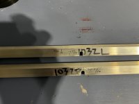
I just wanted to share with the community when creating the left and right longerons (F1032L and F1032R) for tailcone make sure you create mirrored parts. I accidently drilled the 1/4" holes on same side. This created 2 left 1032:-( See picture attached.
This made me have to buy another 98.5" piece of AA:-(
Attachments
jaymark6655
Member
Wing Box J-Stiffeners
Don't nest the long and short stiffener. The long stiffener is flush with the outboard end of the spar and the short stiffener is flush with the inboard end, they just overlap.
Don't nest the long and short stiffener. The long stiffener is flush with the outboard end of the spar and the short stiffener is flush with the inboard end, they just overlap.
jaymark6655
Member
WD-415 Trim Cable Attachment Brackets
Don't rivet the attachment brackets to the E-616 cover plates on page 9-15 step 7. Wait until the cables are set up in section 11.
Don't rivet the attachment brackets to the E-616 cover plates on page 9-15 step 7. Wait until the cables are set up in section 11.
I just wanted to post that I have my complete log, warts and all, at https://www.myeabuild.com/ for anyone that is interested. I am trying to put pertinent comments along with a LOT of snapshots and video.
In addition to the snapshots and archived video, if I am actively engaged in the building process the six cameras I have are live streaming my efforts. I may stop archiving the video on the server at some point because it gobbles up storage space and the snapshots are fairly complete.
I am trying to explain my process and the tools I use with links, as I can. It's pretty time consuming so I hope it is helpful to someone.
I am in the early stages with the tail and have "completed" the vertical stabilizer at this point, partially completed the rudder waiting for a tech counselor inspection, and now working on the horizontal stabilizer...as of this date.
Page 13-2 Step 7 states to clamp long J-stiffener first then nest the short j-stiffener inside the long j-stiffener. As the lengths of long and short will definitely ensure they overlap, it is necessary to nest them. However, the short j-stiffener will be taller than 1/16” where it overlaps.Wing Box J-Stiffeners
Don't nest the long and short stiffener. The long stiffener is flush with the outboard end of the spar and the short stiffener is flush with the inboard end, they just overlap.
Should the taller (about 1/8”) height be maintained for entire length of the short j-stiffener?
Good morning One and all.
First post but been building for three years.
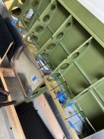
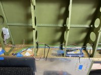
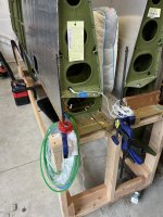
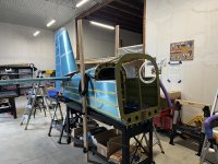
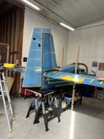
In the process of running wires through the wings and wanted to get some opinions before I close them up. Ran Dynon Pitot and AOA 3 wires to the controller. L wing. Two wires per Vans for stall warn. I want position, strobe, landing light each wing with wig wag. How many wires? Hot only ? Ground to spar? Does wig wag need more? Autopilot ( roll actuator R wing) 3 wires? I’ve also read recommendations to run a shielded higher capacity wire for strobes but then saw (I think AeroLed offering strobes that don’t need higher capacity).
First post but been building for three years.
In the process of running wires through the wings and wanted to get some opinions before I close them up. Ran Dynon Pitot and AOA 3 wires to the controller. L wing. Two wires per Vans for stall warn. I want position, strobe, landing light each wing with wig wag. How many wires? Hot only ? Ground to spar? Does wig wag need more? Autopilot ( roll actuator R wing) 3 wires? I’ve also read recommendations to run a shielded higher capacity wire for strobes but then saw (I think AeroLed offering strobes that don’t need higher capacity).
Attachments
I’ll give this a try. Are you planning on a magnetometer in the wing? If the answer is yes, then you will want to try to reduce magnetic fields from high current wires, e.g., pitot heat, you’ll want to make sure the only ground path is thru a wire, not the airframe (this may or may not even be possible), and you’ll want to twist this wire with the hot wire, all the way back to the main ground buss. For the lights, they draw less current, but I’d bring back their ground returns twisted with the hot wire, just like the pitot heat.Good morning One and all.
First post but been building for three years.
In the process of running wires through the wings and wanted to get some opinions before I close them up. Ran Dynon Pitot and AOA 3 wires to the controller. L wing. Two wires per Vans for stall warn. I want position, strobe, landing light each wing with wig wag. How many wires? Hot only ? Ground to spar? Does wig wag need more? Autopilot ( roll actuator R wing) 3 wires? I’ve also read recommendations to run a shielded higher capacity wire for strobes but then saw (I think AeroLed offering strobes that don’t need higher capacity).
Now, for the lights. I’ll assume you are going to use LEDs. There are two basic choices here. Most use a rapidly pulsed power supply, to keep from overheating the LEDs. At least one company (FlyLeds) uses a dc current and uses dropping resistors to keep from overheating the LEDs. (For strobes everyone has a pulsed power supply, of course). The FlyLeds are electrically ‘quiet’, but do draw more amps than the pulsed lights. So:
For strobes, from any manufacturer, try to bring back a dedicated ground wire. Best is a twisted pair inside a shield. For nav and landing lights: If they use a pulsed power supply treat them like the strobes (individual ground wires, twisted with the power wire, both inside a shield. Some builders have had to put in some extra shielding (thin aluminum plates) around the lights. For FlyLed unshielded power wires and local grounding are okay. Wig wag doesn’t matter.
Follow your LED manufacturer’s guidance when it comes to wire gauge
Bob's comments are spot on, but I would not put a magnetometer in the wing. As mentioned, too much other "stuff" to cause an issue. If you must, place it in the wingtip. That necessitates the GMU-22 non-can bus as the distance gets to long for can bus. I struggled years getting a clean magnetometer interference test mounting the magnetometer per plans before mounting in the wingtip. (RV-14) Mount the GMU-11 (Or Dynan equivalent) behind the rear baggage bulkhead for the 10. Very easy and clean magnetometer interference test.I’ll give this a try. Are you planning on a magnetometer in the wing?
Last edited:
tnelson
Well Known Member
My GMU-11 is in the right wingtip near the trailing edge. The panel builder made the CANBUS length work and mine passes the magnetometer interference test just fine.Bob's comments are spot on, but I would not put a magnetometer in the wing. As mentioned, too much other "stuff" to cause an issue. If you must, place it in the wingtip. That necessitates the GMU-22 non-can bus as the distance gets to long for can bus. I struggled years getting a clean magnetometer interference test mounting the magnetometer per plans before mounting in the wingtip. (RV-14) Mount the GMU-11 (Or Dynan equivalent) behind the rear baggage bulkhead for the 10. Very easy and clean magnetometer interference test.
Works great in flight.
Understand, Garmin has a length restriction of 66 ft and when I calculated my length (RV-10) it would have been close. I know several builders who exceeded the length only slightly and were getting can bus errors. The tailcone of the 10 worked perfectly and easier at least for me. For my 14 I moved the GMU-22 from midwing (plans) to the wingtip as it would not consistently pass the magnetometer interference test. The GMU-22 does not need can bus.My GMU-11 is in the right wingtip near the trailing edge. The panel builder made the CANBUS length work and mine passes the magnetometer interference test just fine.
Works great in flight.
