What's new
Van's Air Force

Don't miss anything! Register now for full access to the definitive RV support community.

What can go next to a GPS antenna?

claycookiemonster

Well Known Member
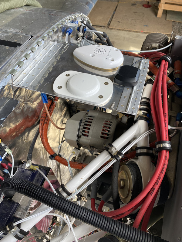
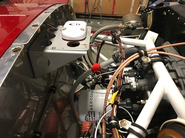
I have my GPS antennas mounted on a shelf projecting forward from the firewall as many others. They will be beneath the cowling. Of course, right beneath the antennas is the whirling mass of the engine, two alternators, 8 spark plug wires and two electronic ignition systems. In an effort to keep things clean up front, I'm tempted to restrain the spark plug wires on adel clamps held to the edge of the GPS antenna's shelf. It makes for a nice arrangement and keeps the wires clear of the alternator beneath and they'll be beneath the horizon of the antenna mounting shelf.

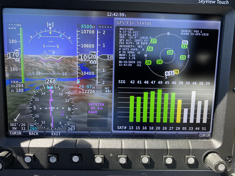
But, will those buzzing wires interfere with the GPS reception?
 
OP here. Just for clarification, here's a photo of the possible set up with spark plug wires being led along the front of the GPS antenna shelf just to keep them out of the alternator and oil filter.
 

Attachments

  • IMG_3178.jpg
    IMG_3178.jpg
    325.7 KB · Views: 73
Clay,

I assume the red ignition wires are associated with an Electronic Ignition. If so, some EIs warn against bundling the wires together (like in your photo) to prevent cross talk. A simple way to do this is add some a clear poly tube over the wire to add separation.

I also suggest that there are better options for mounting GPS antennas. While the close proximity may work on some, if you are using a Garmin TSO GPS navigator (GTN series, GPS-175 or such) they do not play well with other stuff nearby. I suggest moving such Garmin GPS antennas to more benign location - such as on the top of the plane. For GPS antenna/receiver pucks (like the SkyView) there is no such worry. For these mounting on the glare shield is a simple way to go and I consider this a better option than under the cowl.

Carl
 
Here is my setup Clay. Garmin 175, stratus ESG, GRT GPS and ignition wires. 200 hours without any issues.

 
Do those antennas pick up a good signal under the cow like that? or do you have a sunroof that they can see through on your cowl? I'm definitely not a GPS antenna signal expert but never thought they would see through metal cowl. I have a certified plane and don't want to cut a hole in the roof maybe I'll see if I can stick it under it..
 
Do those antennas pick up a good signal under the cow like that? or do you have a sunroof that they can see through on your cowl? I'm definitely not a GPS antenna signal expert but never thought they would see through metal cowl. I have a certified plane and don't want to cut a hole in the roof maybe I'll see if I can stick it under it..

RV’s use a fiberglass cowl. There will be a small shadowing by the metal firewall of satellites that are directly aft and low on the horizon. The big debate is the tolerance of solid state electronics (most of these antennas have pre-amps inside them) to heat.

At the risk of further hijacking Clay's thread ...

As Bob said, RV's have fiberglass cowls. My current RV-8 has the Dynon SV-GPS-2020 GPS ANTENNA/RECEIVER MODULE mounted under the cowl. It has good reception and have not had an issue in 1400+ hours. Don't mount it too close to the firewall to avoid blocking issues, as Bob mentioned.

i-znJ84H3-M.jpg


Screenshot of my typical GPS fix status, which is more than acceptable ('# SATS USED: 8', 'FIX QLTY: 3D' and 'INTEGRITY: YES'). The Dynon manual explains acceptable and unacceptable reception results.

i-WjFNHsN-L.jpg
 
Last edited:
E-Mag spark plug lead guidance

Just got off the phone with the nice guys at E-Mag. Since the question of routing spark plug leads was raised here, though it wasn't the main focus of the post, I thought I'd put the answer to that here in case someone comes searching for an answer.

E-Mag guidance is that the spark plug leads should generally be no closer to each other than 1/4" inch. Hence the zip tie around two leads with a small section of tubing in the middle seen in many places. E-Mag also said the leads could lie directly alongside each other for no more than 6 inches.

In case anyone is asking.
 
I got in touch with both the E-Mag guys and Dynon about separation between ignition and GPS antennas. The E-Mag guys reinforced the ignition wire separation seen in many installation photos with zip ties and a 1/4" section of tubing between.

Just an FYI, the Dynon guys said the separation between ignition leads and antennas of 2-3 ft would also apply to GPS antennas.

That would seem to preclude any GPS antennas placed beneath the cowl and in semi-close proximity to the ignition wires beneath. Even antennas placed on glare shields may not pass that test.

I will file that information away and see how things go with my shelf installation.
 
The big debate is the tolerance of solid state electronics (most of these antennas have pre-amps inside them) to heat.

A bit of thread hijack but since this was mentioned and antenna location is part of the topic.

Highest temp under cowl will be just after shutdown.

Has anyone contacted Garmin to find out the max temp environment that an antenna can be mounted? And….have there been reports of failure due to heat.

It’s got to be fairly high since they make a black one that Stein sells and people use on their glare shield. Additionally, some are painted black when mounted on the glare shield.

Has anyone measured temps at different locations?
 
Last edited:
While under cowl temperature may be an issue, I caution that Garmin TSO GPS navigators have a known problem with RFI generated by NAV/Comms like the GTN-650. When transmitting on the 650 harmonics from the 650 picked up by other avionics then end up swamping the GPS antenna. Result is loss of GPS satellites. This happened to me. In my case the 650 RFI knocking out GPS reception was a temporary Comm #2 radio. The problem went away when I upgraded Comm #2 to the Dynon radio.

The Garmin install manual discusses minimum length of GPS antenna coax. This mitigates the interference as it injects signal loss (here the RFI is the target). The antenna has plenty of pre-amp so no worries about loss of GPS signal from the increased length.

No matter where you mount the Garmin GPS antenna I recommend testing to see if this problem is present. Monitor the GPS satellite page while transmitting, one radio at a time. This is even important if you mount the GPS antenna near stuff.


Carl

Do you still have a 121 Mhz ELT, and where is your ELT antenna?
This sounds like an old problem that many ELT's had.
 
Last edited:
Do you still have a 121 Mhz ELT, and where is your ELT antenna?
This sounds like an old problem that many ELT's had.

This was a new 406MHZ and 121.5MHZ ELT with the ELT antenna at the opposite end of the plane from the Garmin GPS antenna.

Garmin also told me this tale about ELT being the problem. They were wrong. Comm #2 reacted to the harmonic RFI when transmitting on the GTN. As I said, I fixed the problem.

Why Garmin does not put a better front end filter on this very expensive GPS receiver is beyond me.

Carl

It doesn't matter where the ELT antenna is located, it's the unit itself that causes it.
What was the com 2 that caused it? You blame the 650 but replaced the com that actually created the problem?
Welcome to the world of RF radiation, not everything is cut and dry like you think it should be.
 
Last edited:
Please show me the documentation that the antenna coax needs to be a minimum of 3 feet.

I looked at the antenna install manual and did not see it or I overlooked it.

It did state to have a minimum of 2 feet from the GPS antenna to a VHF COM antenna.
 
Please show me the documentation that the antenna coax needs to be a minimum of 3 feet.

I looked at the antenna install manual and did not see it or I overlooked it.

It did state to have a minimum of 2 feet from the GPS antenna to a VHF COM antenna.

GTN installation manual page 3-3. Note there is a minimum loss (dB) specified, which can be accomplished by length, connectors, coax type, etc.
 
Thanks Bob. I still didn’t see 3 feet specified but it did say 6.5 feet if using RG400 (which I am).

Again thanks for info.
 
Back
Top