bbaggerman
Active Member
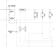
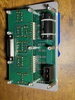
I am in the process of redesigning my legacy RV-12 electrical system. To free up more panel space I am going to replace my Van's Fuse and Switch Module with a Vertical Power VP-X electronic circuit breaker box. Besides switches and fuse, the Van's panel apparently also has a current sensing shunt. I say apparently because I'll be darned if I can figure out where it is. I was expecting to find an appropriate copper shunt with sense wire whiskers on it but so far no joy. Is it possible they implemented the current sensing shunt with just a PCB trace? Using a PCB trace for current sensing is notoriously inaccurate but maybe accuracy isn't that big of a deal. Still...
Anyone know where the current sense element is in the Fuse and Switch Module?
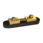
Anyone have an recommendations for an external current sensing shunt for use with the VP-X ECB?
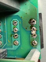
Attached are a few pictures for reference. BTW, that last picture I attached is some less than acceptable soldering I found on my panel. This solder bridge shorted around the 30 amp generator fuse. Nice!
Anyone know where the current sense element is in the Fuse and Switch Module?
Anyone have an recommendations for an external current sensing shunt for use with the VP-X ECB?
Attached are a few pictures for reference. BTW, that last picture I attached is some less than acceptable soldering I found on my panel. This solder bridge shorted around the 30 amp generator fuse. Nice!