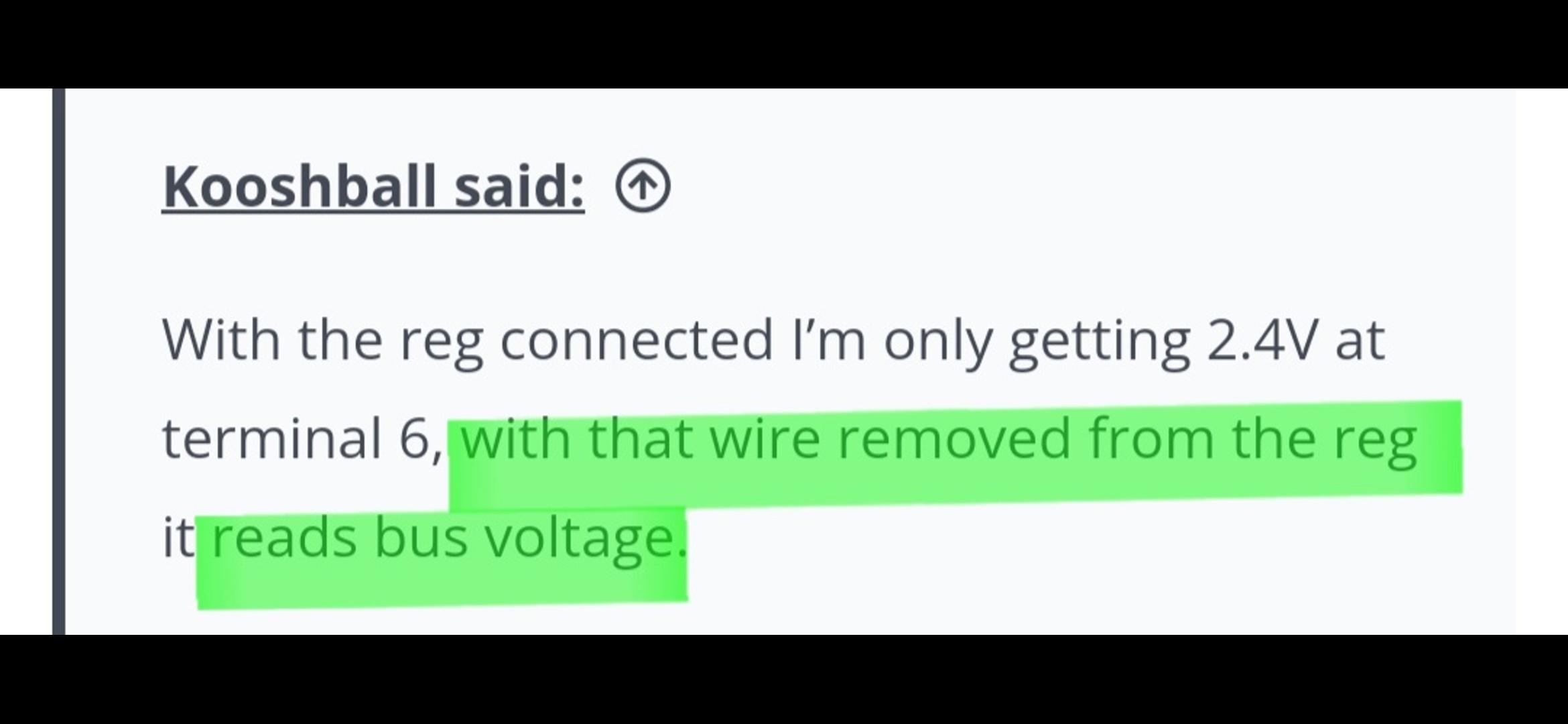
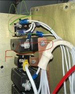
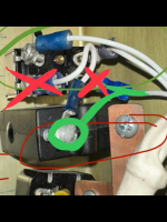
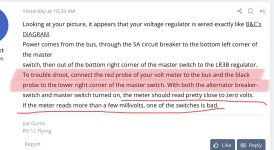
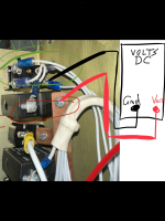
I am troubleshooting an issue preventing the correct voltage from reaching my B&C voltage regulator. In trouble shooting the alternator field switch in the panel, I found it wired as shown in the photo. The “M” is the master switch and the “F” is the field switch with is actually a 5a toggle breaker.
I am trying to understand why the field switch is connect to the bus and the master rather than being connected directly to the voltage regulator as shown in the recommended wiring diagram from B&C.
Any thoughts on this installation?
Thx!
I am trying to understand why the field switch is connect to the bus and the master rather than being connected directly to the voltage regulator as shown in the recommended wiring diagram from B&C.
Any thoughts on this installation?
Thx!

") No remembering and subtracting required.
No remembering and subtracting required.