What's new
Van's Air Force

Don't miss anything! Register now for full access to the definitive RV support community.

Please Critique my SDS RV14 Electrical System

TASEsq

Well Known Member
Patron
Hi Brains Trust,

I am working on planning out my RV14 electrical system, with the following design goals / features:
- IFR
- Garmin G3X with IFR Nav
- SDS EFI Fuel Injection / Ignition
- Single Battery
- B&C 60amp Main alternator
- Monkworkx 30amp alternator in Backup mode.
- The system needs to be passive - no failure can require pilot action to keep the engine going
- The system needs to handle failures such that i can be IFR/IMC at night and can still have what i need to safety fly a GPS based approach.
- It needs to be bog simple and intuitive. Turn all the switches on, leave them there and go flying.

To this end, I have been working on planning out the system using KiCAD as my planning software, and an Excel based workbook with each wire/group listed as equipment to equipment / pin to pin etc. It's here i am doing load analysis etc, and will eventually do a failure analysis. It is helping me to calculated what supplies i need to order.

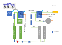
Attached is a basic block diagram of the system, with a few KiCAD excerpts showing the main electrical generation schematic, as well as the SDS EFI wiring schematic.

The design is based on the great work by John Bright - thank you for the inspiration!

The design has the following notes:
  • - A single dedicated engine bus fuse block located behind the panel feeds the engine electronics. This will live close by the SDS ECU / Relay box, and will be visible for pre-flight checks of the fuses. I will likely used a Bussman or Bluesea fuse block - i am happy that these are robust enough not to be a SPOF. (plus the injectors only have a single source of power anyway).
  • - This bus is fed by the battery through a relay, or fed from the monkworkx generator, or via a diode from the main bus (and main alternator). (3 sources of power).
  • - The relay is needed between the battery and the engine bus because i believe the Monkworkx will have a parasitic drain otherwise.
  • - An Essential bus, is fed from the engine bus at one end, and the main but at the other end. This gives power to the basic IFR instruments (GAD27 - which feeds keep alive power to PFD, GEA24 etc, as well as G5, NAV, 1 x com, cockpit lights, Autopilot etc). This is a CB fed bus located where the RV14 circuit breaker panel is.
  • - On the main bus / main fuse block is everything else in the aircraft. The main fuse block will only be installed if i run out of CB's on the main bus. This is also located on the RV14 Circuit Breaker panel area.
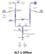
  • - The idea is that any of the 3 DC source switches can be on in flight, and i will have the engine bus and minimum IFR instruments.
  • - In normal ops, all 3 DC source switches are on at all times.


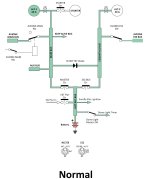
The normal use scenario is as follows:
  • - Normal ops will see the ENG/ESS BUS - BATT and GEN switches turned on. This will power the engine ECU's, and basic instruments from the battery. One fuel pump is turned on. Both ignitions are turned on and engine is started.
  • - The monkworkx should then take over supply of the eng/ess bus and show it is working. The ENG/ESS BUS - BATT switch could be turned off as a test to check the Monkworkx can handle all engine/ess loads.
  • - The MAIN BUS BATT/ALTN switch is then turned on and the main alternator takes over, and the monkworks goes to sleep, checking the main alternator is working.
  • - Runups would include swapping fuel pumps (and leaving them swaped to even out the duty cycles on the pumps), checking both ignitions. Swapping ECU switch to backup then back to primary. At this point no switches need be touched on the left switch panel until shutdown. Runup is simple really.
  • - For normal ops, the main alternator would be feeding the main bus through a 70amp MIDI and a shunt, and through a diode the essential bus. Since the engine bus is connected to the essential bus, the main alternator would also supply the engine bus. As an additional pathway, the main alternator also supplies the engine bus through both battery contactors (aka dual feed pathways to the engine bus).
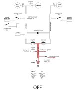
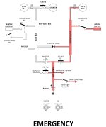
  • - In a cockpit smoke scenario, or the main bus faults, the MAIN BUSS BATT/ALTN switch is turned off. This kills power to the main bus and everything except the essential items. I can then pull CB's on the essential bus, as required, if the smoke persists.
  • - If the main alternator fails, the monkworkx passively takes over as the voltage drops to battery volts (with a CAS message etc).
  • - If the battery catches fire, i can turn off both battery switches and the monkworks powers the engine and essential items.
  • - If the essential bus faults - then i kill the main battery switch to turn off the main buss and it's supply to the essential bus. Do i need to place a relay inline between the engine bus and the essential bus, such that power flows through the normally closed contacts, and a "shed" switch to turn off this bus? Or just pull the 5-6 breakers along the bottom row? This will be fed with a fuseable link from the engine bus to protect it's feed wire, and from the main bus through a diode the wire will be short. But nothing really protects the essential bus itself from a short? (this will be CB's and a copper bar).
  • - If the engine bus faults - will then i have an issue. But i think this is a low risk event. I will use a sealed automotive fuse block. What could really go wrong with this?
  • - For those who have installed the Monkworkx, do i need the 30amp MIDI on the feed line from this generator? Or is it fuse protected internally?
  • - There are probably many failure points i have not considered!
  • - I was thinking for the 2 battery 'contactors' that i would use some Gigavac relays instead. I don't really see why i need the old tin can versions? Why not just a relay?

I know asking people to review my electrical system is a big ask - i am totally open to criticism and will happily take on all comments. I have an open mind as this is my first attempt at something like this. My aim here is to flesh this all out and try and think of as many gotchas now before i even get close to running wires.

Thanks in advance to the brains trust for your help and assistance. If anyone wants any more detail etc just ask and i will make a follow up post.
 

Attachments

  • Block Model - Basic V1.pdf
    235.9 KB · Views: 241
  • Master Wiring Drawings-Electrical Generation.pdf
    390.5 KB · Views: 177
  • Master Wiring Drawings-SDS EFI.pdf
    1.3 MB · Views: 95
  • Master Wiring Drawings-Left Panel (LP).pdf
    2.4 MB · Views: 88
Last edited:
Boost Pump comment

Trent: I recommend you reconsider the boost pump function.

It appears to be an (added) single point of failure, with limited value: the fuel system would be usable by other pilots without this function, and YOU don't need it, as you already well understand normal, emergency, and maintenance procedures of the fuel system.

(I have a limited perspective, as I'm building, not yet flying, a very similar RV14A: IFR, G3X, SDS EFII, single battery, B&C 60A main; Monkworks 30A backup alternator...)

Thanks for thinking this through and asking for reviewers; I'll be watching for other input!
 
Trent,

Before digging too deep, some questions and comments:
- Your first diagram and second diagram do not agree. Follow the battery connections that bypass the two solenoids. You have the starter solenoid always connected to the battery as your copper bar bypass the other two solenoids. Here you have no way to isolate the aircraft from the ship battery.
- Most people start the engine via power from the battery on the output side of the master solenoid. This also provides a means to isolate the big wires in the event of an electrical fire.
- I would not think a single ship battery ship, regardless of the backup generator scheme to be adequate for an electrically dependent engine and IFR.
- Your dependence on the Monkworz generator is noted. I fly with one as well (two battery, split buss system, pMags and traditional fuel injection). I know it works as I test it. In my case I have additional backup modes to support continued IFR flight to fuel exhaustion. For you I suggest a rigorous test program that starts with opening the master solenoid (after you rewire it to really isolate the battery) to verify the system works as you think it will.
- While you note you have three DC power sources you may only have two (the battery and the Monkworz). The primary alternator may not work without a battery on line - I don’t know you will need to verify it.
- The last issue is about power distribution. Most issues I run across that result in a dark panel have a root issue of getting power where you need it, not a lack of a power source. After you get your final design locked down look at the power flow - and what can fail that will turn it off. This includes relays, diodes, ground connections, etc. Here is where a two battery system may provide advantage.

Carl
 
Why only a single battery?

I have a similar setup, dual battery and dual alternator and full SDS EFI&I.

One battery and one alternator (B and C SD8) are dedicated to the engine and the panel.

Second battery and main alternator (B and C 60A) are dedicated to the rest of the plane----AND feed power to the first circuit through a Shottkey diode. All items not needed to keep the engine running and the EFIS's lit up run off this second circuit.

One benefit of this design is the ability to power up the EFIS first, then start the engine from the second battery and I never see a panel brown out due to starter current draw, and I have all engine parameter gauges up and working during the start.
 
The single battery becomes a SPF though many will argue to the contrary. Even extensive testing for your alt or gen to stay on-line with a bad battery doesn't necessarily mean anything. A "pass" means it stayed on line on that day, under those exact variables. A quick change in load from a comm xmit, flap actuation, pump actuation, etc./vice versa -> undamped load swing -> blackout.

Batteries are cheap; or not-so-cheap but very light weight. Gage your risk.
 
I am surprised no one has commented on your alternator connection. You have it directly connected to the main bus relay, without protection. Yes, alternators fail sometimes.

Normally, the alternator connects to a shunt, then an ANL fuse or circuit breaker, then to your main (Master) bus. (You can reverse the two if you want).

See http://www.vx-aviation.com/sprocket/photos/panel_elec/schematics-2/MASTER.pdf

or reference Bob Nuckolls aeroelectric drawings http://www.aeroelectric.com/PPS/Adobe_Architecture_Pdfs/
 
Similar Setup

I do have a very similar setup. My TT is 25hrs so not much real world experience..

-single battery
-dual alternator
-1x SureFly Mag (electr. dependent)
-1x classic Mag (if all elec fails, this should keep the fan spinning)
-G5 Standby EFIS with its own backup battery
-the Main Bus feeds the ESS Bus via 2 parallel Schottky Diodes any time the MASTER Switch is set to BAT
-During NORMAL Operations both the Master Switch and ESS Switch are set ON (the Master Contactor and ESS Contactor are closed with both Alternators armed (the Main Alternator is set for higher voltage / has priority)


I'm wondering if there would be any disadvantage if the MASTER Switch would power both the MASTER Contactor and the ESS Contactor at the same time.
- This would avoid the diode voltage drop on the ESS bus as long as the ESS bus is not powered by its own Contactor.
- Should the ESS Contactor fail, the Diodes will take over.
- I could still preflight-check the Diodes operation if I power the ESS Contactor only (no reverse flow to the Main Bus).
 

Attachments

  • OM-ELA PGDS ver.4 OFF.jpg
    OM-ELA PGDS ver.4 OFF.jpg
    133 KB · Views: 68
  • OM-ELA PGDS ver.4 NORMAL.jpg
    OM-ELA PGDS ver.4 NORMAL.jpg
    133.8 KB · Views: 67
  • OM-ELA PGDS ver.4 ALT-1 OFF.jpg
    OM-ELA PGDS ver.4 ALT-1 OFF.jpg
    137.2 KB · Views: 49
  • OM-ELA PGDS ver.4 EMERGENCY.jpg
    OM-ELA PGDS ver.4 EMERGENCY.jpg
    139 KB · Views: 54
You might want to use a fuse upstream of the diode. If you get a short on the essential bus, the 10 ga wire (or the diode) will become the fuse, opening before the 70 A MIDI fuse. Going to a larger gauge wire won’t help because if the 70 A MIDI blows due to an ess bus short, both buses would go down.

The MZ-30L has a 30 A output fuse so in theory you don’t need an extra fuse on the output.

-Bob
 
Firstly, thank you all for the initial look at the system. I will try and give some more info below, but again open to discussion! I truly appreciate all the assistance.

The 'block diagram' was a quick and dirty representation i made (in word!) of the system to help explain how it works and assist this discussion - i messed up a few things on it, and it's been corrected and V2 attached.

Single Battery: This is a great discussion. I went back and forth, around and around about this. Initially i had a B&C backup alternator in the system - that for sure would mean a second battery is required, as (same as the primary) it needs a battery in the system to work properly. But the Monkworkz has changed my thinking totally - it is like having a second battery in the system, however it does not run out of juice. It is able to run by itself, with no battery present. I am able to totally isolate the 'main bus' side of the system, then disconnect the battery from the ENG/ESS bus side of the system, and the Monkworkz can power all of the essential loads without a battery present.

The thinking on not going with the 2 batteries was mostly that the batteries (EarthX) are very expensive. They are also consumable, and impossible to get when away from base. I have worries that something would happen and the BMS would switch both of them off. Hard to buy in Australia. Also, on the RV14 i haven't been able to find anyone who has a good location for the battery - Andrew Kilroy has used 2, and placed his high on the left hand side, so that is a possible location, but i would need to really have the engine hung to know.

I know the Monkworz is a new player - but it really seems to change the game for electrically dependent engines. Have i got too much love for the unit? In my scenario, to end up on the single battery only i would have to have both a main alternator and the Monkworkz fail (and both sources get tested every flight). If the battery itself failed, i would be on the Monkworkz alone - but this would be enough to fly until the fuel ran out.

Keen to continue the discussion on this, as i am not wedded to my system design by any means.

Trent: I recommend you reconsider the boost pump function.

It appears to be an (added) single point of failure, with limited value:

If you take a look at the SDS design page, there is an explanation of how the 'boost pump' works. The SDS has 2 fuel pumps, and one runs all the time. The other is able to be used for take-off and landing as a backup should the main fail. In my system, both the pumps are run through relays - on the normally closed contacts. Similar to how the injector relays work in the SDS design. Aka, they run all the time unless you ground the relay. The 'boost pump' switch is where this ground comes from. With it selected 'off' there is a ground available to both of the fuel pump switches. Meaning, when i select one or both of the boost pump switches to off, they connect to the ground which comes through the 'boost pump' switch. Turning the boost pump switch 'on' simply removes the ground from both the pumps, so they turn on. This is a passive failure system. The failure of any fuel boost pump switch, the electrical failure of a relay, failure of the boost pump switch, or loss of both the grounds off the boost pump switch, all result in the fuel pump running. A total physical destruction of the fuel pump relay might render the pump US. I was planning on placing them in different locations in the airframe (10" apart or something). I liked this design as it was similar to most other commercial aeroplanes - turn the boost pump on for take-off or if something happens. Yes - i could also just turn on the other fuel pump switch to achieve the same thing - but i like the idea of never having to touch a switch on the left hand engine switch panel in flight. Less likely of turning off an ignition after takeoff!

- Your first diagram and second diagram do not agree. Follow the battery connections that bypass the two solenoids. You have the starter solenoid always connected to the battery as your copper bar bypass the other two solenoids. Here you have no way to isolate the aircraft from the ship battery.
- Most people start the engine via power from the battery on the output side of the master solenoid. This also provides a means to isolate the big wires in the event of an electrical fire.

Thank you - this is corrected in the block diagram V2. The KiCAD diagrams show it properly. The power for the starter comes from the 'downstream' side of the ENG/ESS bus relay.

- Your dependence on the Monkworz generator is noted. I fly with one as well (two battery, split buss system, pMags and traditional fuel injection). I know it works as I test it. In my case I have additional backup modes to support continued IFR flight to fuel exhaustion. For you I suggest a rigorous test program that starts with opening the master solenoid (after you rewire it to really isolate the battery) to verify the system works as you think it will.
This would be normal ops i think. I would start the engine with the MAIN BUS totally off. After the engine runs, I should see the volts increase and the Monkworkz power the system. I can turn off the ENG/ESS bus battery switch to truly test this. This is the reason there are 2 switches for the ENG/ESS bus (as the monkworkz can run by itself without a battery), but a progressive switch for the MAIN BUS side (as the B&C alt needs the battery to run).

- While you note you have three DC power sources you may only have two (the battery and the Monkworz). The primary alternator may not work without a battery on line - I don’t know you will need to verify it.
You are probably right here. Both the battery and the Monkworkz can be used standalone, but the alternator needs the battery.

- The last issue is about power distribution. Most issues I run across that result in a dark panel have a root issue of getting power where you need it, not a lack of a power source. After you get your final design locked down look at the power flow - and what can fail that will turn it off. This includes relays, diodes, ground connections, etc. Here is where a two battery system may provide advantage.
Thank you - this is my plan. Once i flesh out a design, i will make up a table where i fail one thing at a time and log what would happen. It may required changing the system design.

I am surprised no one has commented on your alternator connection. You have it directly connected to the main bus relay, without protection. Yes, alternators fail sometimes.
Thank you - this was an error in the block diagram. On the proper diagram i have a #10 fuseable link on the B lead feed to the hot side of the the MAIN BUS contactor. My thinking was that this then protects the B lead from shorts to the main contactor. From there i need to protect the #6 though the firewall - this was the job of the MIDI. I had based this on the Z101 - this has a #12 FL on the B lead to the starter contactor (at the contactor end). He then had an unprotected #4 between the starter contactor and battery contactor (this is ok because it is short), then (strangely??) no protection on the #6 feed from the hot side of the battery contactor to the main bus. I didn't think this was a great idea, so added the 70a midi.

I may be totally misunderstanding how these protections are supposed to work of course!!!

By swapping them, do you mean i could have the shunt / midi in either order?

[Edit - text too long. See second post]
 

Attachments

  • Block Model - Basic V2.pdf
    246.4 KB · Views: 66
Additional post due text too long!

You might want to use a fuse upstream of the diode. If you get a short on the essential bus, the 10 ga wire (or the diode) will become the fuse, opening before the 70 A MIDI fuse. Going to a larger gauge wire won’t help because if the 70 A MIDI blows due to an ess bus short, both buses would go down.


This is interesting. So if the essential bus shorts, the #10 feed from the main bus to the essential bus would go down before the 70amp midi? I think this is what i would want to happen? This would mean the main bus would remain powered. The essential bus is also fed from the engine bus, but there is a fuseable link on this feed line, so this would also blow, isolating the shorted essential bus.

Perhaps a #14 fuseable link on the short #10 feed from the main bus, through the diode to the essential bus is a good idea? If the essential bus shorts, then this fuse link goes to stop flow from the main bus, and the fuselink on the feed from the engine bus also goes - isolating the shorted bus automatically? Am i understanding this ok?

If the main bus shorted, then the 70amp midi would blow, isolating this bus (as the diode is there to stop current flow from the essential bus back to the main bus).

The MZ-30L has a 30 A output fuse so in theory you don’t need an extra fuse on the output.

I was not totally sure about the 30amp midi to be honest. I will be flying with both battery contactors open. This means that the essential bus will be powered by the main alternator most of the time. There are 2 feed paths - one is via the diode from the main bus, the other is through the 2 contactors to the engine bus, then the essential bus.

Should the power feed from the Monkworkz the the ENG/ESS bus contactor short - the fuse in the Monkworkz will protect the line. However, since the feed line to the engine bus is connected to the hot side of the ENG/ESS bus contactor, and this is getting fed from the alternator - i thought that if this line was to short, it would not be protected by the Monkworkz fuse. It needs the 30amp midi to protect this line from a short?

Does this thinking made sense?


Thank you all for your feedback so far. Please see amended V2 of the block diagram. The KiCAD source diagrams are unchanged at this point, however will consider the fuseable link between the MAIN BUS / ESSENTIAL bus feed as discussed above.
 
Which circuit protection would blow?

In the scenario below, I've indicated a wire which is the #10 connecting the engine bus to the essential bus. This wire run would go from behind the panel to the CB panel, so would be protected by a #14 fusible link.

If this wire shorted - how can i be sure that the #14 fusible link would blow, before the 30amp midi which is on the feed to the engine bus?

Or is there no guarantees? (and i need to re-think the way the essential bus is fed).

Since this wire could potentially have power running in either direction, does it need a fusible link at both ends?
 

Attachments

  • Screenshot (95).png
    Screenshot (95).png
    95.4 KB · Views: 45
Last edited:
In the scenario below, I've indicated a wire which is the #10 connecting the engine bus to the essential bus. This wire run would go from behind the panel to the CB panel, so would be protected by a #14 fusible link.

If this wire shorted - how can i be sure that the #14 fusible link would blow, before the 30amp midi which is on the feed to the engine bus?

Or is there no guarantees? (and i need to re-think the way the essential bus is fed).

Since this wire could potentially have power running in either direction, does it need a fusible link at both ends?

A 14 awg fuselink melts at about 166A and a 10 awg feeder melts at about 333A.

Re schematics in posts # 11 and #1. If I were doing the FMEA for the normal flight ops case with engine bus relay closed and the failure mode is feeder from essential bus to engine bus shorts to ground, I'd say the effects are certain loss of engine power, certain loss of essential bus, and high probability of loss of main bus. This is because the 30A MIDI to the engine bus relay will open followed by either the 70A MIDI between main bus and master contactor or the diode between main bus and essential bus. The 14 awg fuselink at the engine bus serves no purpose.

So this line on the FMEA calls for a redesign. Likelihood is low with best practices installation techniques but the effects are critically bad and a more robust design can be achieved.

What I plan is engine bus FWF fed from opposite ends. Engine bus relay and PM generator on one end and diode to master contactor switched contact on the other end. Both feeds unprotected and constructed in such a way they are easily inspectable and the likelihood of shorting to ground is nil. I have a simplified brainstorm schematic I call "Elec Schem Monkworkz MZ-30L on engine bus Config 5". At present it's in folder 1) / A) / Production Intent here.

I put Com 1, trim, transponder, defrost fans, and interior/map/IP/glareshield lights on the engine bus and the two Skyviews and the AV-30 are self-powered. I'm assuming those resources will get me down safe. I'm a low-time VFR pilot though so I'm ready to learn if that is not true in the OPs night IFR case.

PS 1: The diode is an artifact of Z101. I left it in for the case of engine bus relay failed open the engine would quit at idle because the PM generator does not make enough current. It the diode weren't there I would feed one end of the engine bus with the engine bus relay and the other end with the PM generator.

PS 2: In the OP's smoke-in-the-cockpit-main-master-off failure mode... with the essential bus and the engine bus powered by the PM generator and the battery present... consider turning off one coilpack one fuel pump if you need current for flight-critical devices and you don't want to run the battery down.

PS 3: I have only two reported data points for the 14V Monkworkz MZ-30L on a Lycoming... 15A at 1,000 RPM and 30A at 1,800 RPM and above. My information indicates it takes 14.2A low altitude, 9.0A cruise, and 7.9A endurance (one coilpack off, one pump off) to run a four-cylinder Lycoming, ref my load analysis in folder 3 here.
 
Last edited:
Thank you for your feedback.

A 14 awg fuselink melts at about 166A and a 10 awg feeder melts at about 333A.

Re schematics in posts # 11 and #1. If I were doing the FMEA for the normal flight ops case with engine bus relay closed and the failure mode is feeder from essential bus to engine bus shorts to ground, I'd say the effects are certain loss of engine power, certain loss of essential bus, and high probability of loss of main bus. This is because the 30A MIDI to the engine bus relay will open followed by either the 70A MIDI between main bus and master contactor or the diode between main bus and essential bus. The 14 awg fuselink at the engine bus serves no purpose.

So this line on the FMEA calls for a redesign.

Thanks for your feedback John! I had reviewed both your config 5 and Z101 when working on this design - i had practicality of construction in mind in the design. I.e. It would be physically easier to feed the ENG bus from the main bus through the ESS bus.

However, when i went back last night (14 hours in the back of an A380 is a lot of thinking time!), i realised this seemingly insignificant design choice really changed the fundamental way Z101 (and your design) worked. A small change has big consequences! I drew out a basic block diagram of Z101 to see what i had mistakenly done.

So, based on this, i think it is best to feed the engine bus with it's own feeder off the MAIN contactor, not from the MAIN bus. See attached.

Out of interest, i have been considering the 2 battery option. In the current design, i can't really find a spot to include the 2nd battery and still have the Monkworkz be able to power the main bus side of the system (the diode prevents it). Interested in your thoughts.
 

Attachments

  • Block Model - Basic V3.pdf
    315.3 KB · Views: 48
Dual bus?

Given that you have two ECU's, two coil packs, two fuel pumps and now you are considering dual alternators/dual batteries - why don't you do a dual bus system where the SDS components are fed from their individual hot battery busses? The fuel injector power is a little more complicated as the 4 cylinder model does not have the dual power input relay box like the 6 cylinder.

I know that doesn't solve your other design criteria, but it possibly makes keeping the fan turning a bit simpler.
 
+1

Given that you have two ECU's, two coil packs, two fuel pumps and now you are considering dual alternators/dual batteries - why don't you do a dual bus system where the SDS components are fed from their individual hot battery busses? The fuel injector power is a little more complicated as the 4 cylinder model does not have the dual power input relay box like the 6 cylinder.

I know that doesn't solve your other design criteria, but it possibly makes keeping the fan turning a bit simpler.

This might be a better approach and I agree 2 batteries is better with an electrically dependent engine. The B&C engineers were quite insistent that if your battery BMS went off-line (low probability) the alternator might not be ok. Plus with 2 batteries you would have more time to find an alternate airport to land. With todays electronics if an alternator fails you should know within seconds of the failure. I’ve tested mine (RV-14A) every 3 months and literally within seconds I know. (Amp and voltage alarms).

I’ve added a cross-tie (In my 10 build) able to manually cross the essential and primary bus and the plan would be to activate on the ground after landing if needed to get home or charge on the ground.

Basically I’m using a Z-14 drawing as found on the B&C website.

Not sure whose contactors you are using but Gigavac makes some very nice recent technology models

Regardless review KatanPilot input.
 
Last edited:
I hope folks don't lose sight of the fact that all this added complexity (both mechanically and electrically) may be 'fun' to ‘tinker’ on, but the reality is you get a much more complex machine with more failure modes and questionable reliability compared to the age-old simple proven FI/Mag system with perhaps a single EI.
And if someone says one more time I'm doing this because it starts easier, I think I'll kill myself. :D

If you ever have a problem (which will happen), you'll be the only one that knows how to work on it, expect little help from outside sources so you better be an expert.
When/if you want to sell the aircraft it will likely will not be considered a desirable feature.
 
Last edited:
Trent,

You are still using a big fat copper bar to bypass the master soleinod to go to yet another solenoid, then a starter relay for engine start. No reason to do this, and you add risks (those big fat copper bars always bothered me).

Run the starter relay directly off the output of the master solenoid. You can then feed the engine solenoid via a #10 wire from the battery(s).

I also suggest replacing the single, big engine solenoid with perhaps two 60amp relays to feed you electrically dependent engine.

I have designed a power districution system for electrially dependent engines, but it requires two identical batteries. Adding the MonkWorx is never a bad idea.

Carl

Carl’s electrical architecture co-op’d for EI attached below. He is a PMag, mech FI guy. This was labeled a “mistake” or similar by some as too complicated. I disagree.
Lose a bus = no pilot action required.
Lose your active wattage sources = non-essential is shed when the masters are opened.
No expensive back-up batteries are required as you have independent sources (e.g G5). Relatedly, many of the other Garmin black boxes have dual, dioded inputs like the aforementioned to take advantage of such approaches.

Some have done very similar approaches but utilized diodes instead of relays. To each his own. Some like me prefer the ability to easily test functionality in a preflight and have control over isolation. So to the OP, you appear to be looking at a lot of different sources/approaches. Good. There’s something to be learned from most of them. If there are any perfect one, they’d all look the same.


Consider Walt’s comment. If you have no desire to utilize different fuels (octanes) there’s nothing wrong with mechanical devices for engine ignition/injection. Then you only have to worry about the required for you intended mission.

Enjoy. Let us know where you end up.
 

Attachments

  • Power Dist SIngle LIne Functional.pdf
    86.7 KB · Views: 46
Thank you all for your replies.

Please don't think i am defending my system - i am not. I am open to other ideas and i've been thinking on each and every opinion below.

Regarding the split / isolated bus concept. I agree totally - if the SDS injectors had 2 sources of power it would be a no brainer. Run half of the system on 2 busses. Since the injectors have a single power source, i elected to go with a single engine bus fed by multiple sources instead. I don't feel that the single bus physically adds much risk - i was planning on a good quality bussman used in hundreds of vehicles (and in much harsher environments). Located behind the panel where it is clean and dry (and inspectable at prefight - red light = blown fuse). I think I am comfortable that this single bus is robust enough. Having multiple sources, joining physically at opposite ends of this bus achieves the same thing (i think?).

Is there any additional safety value achieved by running 2 fuse blocks, and duplicating wire runs to the injectors? (and splicing the 2 sources into a single wire close to the injector?) - the splice / solder itself may be a source of failure.

Regarding the 2 batteries - those comments are spot on i think in cases where the battery needs to be present for an engine driven power source to work. In this case, the Monkworkz does not need a battery. So you could think of it like a second battery which has an unlimited capacity. It won't help me on the ground if the main battery is offline / flat - but then i don't want to go flying anyway. If i had to kill power to everything but the most essential engine / avionics, then the monkworkz should be fine on its own from what i have read. It is directly connected to the engine bus with no switches or relays.

The note about added complexity of the EI system is noted. It is somewhat of a 'this is cool' factor - however the main driver (no, it's not hot starting - i can start a Lyc hot!) is the antipodean fuel supply downunder. I don't want to end up not being able to get Avgas one day and i can't fly my machine. I would prefer to be able to run Mogas (hence the requirement for SDS etc).

You are still using a big fat copper bar to bypass the master soleinod to go to yet another solenoid, then a starter relay for engine start. No reason to do this, and you add risks (those big fat copper bars always bothered me).

Run the starter relay directly off the output of the master solenoid. You can then feed the engine solenoid via a #10 wire from the battery(s).

Thanks Carl. I appreciate your feedback and your experience. However, i think my system is exactly as you have described? If you imagined the schematic with the battery on the "ENG BUS" relay, and the copper bar as a #10, then the system is electrically identical (unless i am missing something). Is it better to connect the battery to the post of the "ENG BUS" relay? I can't imagine how a copper bar could fail?

In my design, there is no 'master contactor' per se. Aka a single contactor which joins the battery to the whole aircraft. I have thought about it in the reverse sense - one battery with 2 contactors. These contactors connect the busses to the power source (battery).

You could consider my system with the "ENG BUS" relay as being the traditional 'master contactor', and the "MAIN BUS" relay like an avionics relay if you liked. It is a similar concept. The engine bus will have all the SDS components, and the "ESS BUS" has the minimum avionics for safe IFR flight. The "MAIN BUS" has everything else.

Why not just have all the critical stuff on the Engine Bus? I am thinking about smoke in the cockpit. The Engine Bus will be a fuse block behind the panel. The Essential Bus will be 5-6 breakers in the cockpit. If i have smoke, i can kill the "MAIN BUS" (and alternator in the same switch) and most things will go dead. Then, if there is still smoke i can selectively remove power (pulling breakers) from the remaining avionics, keeping in mind i may need some of this for IFR.

Operationally you would start the engine by connecting the battery to the engine bus through the "ENG BUS" relay. Once started i can turn on the separate GEN switch and verify the Monkworkz is working (it should do 15A to power everything at 1000rpm). I would see a voltage rise on the engine bus from the battery level as verification (and a CAS message would go out). I can then give the main bus power by connecting it to the battery (and the Monkworkz) and the rest of the panel lights up and is powered by the Monkworkz / Battery. I then turn on the ALT switch and the main alternator takes over the whole load, and the Monkworkz goes back to standby. I should see a further increase in volts on the engine bus. During runup i can close the "ENG BUS" Relay / Monkworkz GEN switch and check that the engine bus is fed by it's alternate feed (checking the integrity of this backup line / the 30a MIDI etc). If the engine stops when i do this, i know this alternate feedline and/or diode are bad and i don't go flying!!

As an aside, i don't think i will necessarily use the traditional contactors (cans). I was thinking a Gigavac relay for both the 'contactors'. The copper bar would be a simple way to just join the posts of these relays - maybe 3" long maximum covered in heat shrink. I thought this was a common way to join contactors (or contactors / starters)?

This one is 250A continuous, with 500amps if using 4awg.
https://www.bluesea.com/products/9012/Solenoid_L-Series_-_250A_12_24V

I will think more on your idea of multiple redundant relays instead of a large one for the engine bus. In the schematic however it would not matter if the "ENG BUS" relay failed - the Monkworkz is directly connected to the Eng bus at all times. The starter is the issue - if i used multiple lower rating relays here, the starter could not be run through those relays. Meaning i would need to rethink how i checked the system serviceability on startup to make sure i don't end up with a hidden blown fuse or diode etc (as per N811HB).

Thanks all for your help! Please don't think i am defending my position - i am most certainly open to other ideas, and pulling apart my design helps me to learn more on how things work and i can flesh out the issues before a wire is even ordered.

Happy thanksgiving to those who are in the US. [turkey emoji]
 
Why 2 identical batteries ?

Trent,

I have designed a power districution system for electrially dependent engines, but it requires two identical batteries. Adding the MonkWorx is never a bad idea.

Carl

Carl why 2 identical batteries ? Both Cathy at Earth X and B&C have told me mixing a ETX 900 and 1200 are ok together.
 
Last edited:
Carl why 2 identical batteries ? Both Cathy at Earth X and B&C have told me mixing a ETX 900 and 1200 are ok.

I use two PC-625 batteries. This is for backup mode design objectives and maintenance, not because of any consideration for charging.

I find the PC-625 to be a nice choice for this application. The form factor makes for mounting options, it is a pound lighter, has more CCA and AMP-HRs than the PC-680.

I replace one of the two batteries every three years. This results in the oldest battery not exceeding six years. This provides some confidence in reserve electrial capacity. Pulled batteries go on for a second life in the various yard tractors and such.

Carl
 
Thanks

I use two PC-625 batteries. This is for backup mode design objectives and maintenance, not because of any consideration for charging.

I find the PC-625 to be a nice choice for this application. The form factor makes for mounting options, it is a pound lighter, has more CCA and AMP-HRs than the PC-680.

I replace one of the two batteries every three years. This results in the oldest battery not exceeding six years. This provides some confidence in reserve electrial capacity. Pulled batteries go on for a second life in the various yard tractors and such.

Carl

Always appreciate your input.
 
Thank you all for your replies. .

……Regarding the 2 batteries - those comments are spot on i think in cases where the battery needs to be present for an engine driven power source to work. In this case, the Monkworkz does not need a battery. So you could think of it like a second battery which has an unlimited capacity. ……It won't help me on ….

Forgive me. Probably being my typical blind-@ss self. I’m aware of the advanced control methodology/electronics but I could not find where the MWz released info states it does not need a battery for operation. A little bit surprising if true. Very surprising in such a litigious country and application field. Maybe Mr. Judge will comment directly.
 
No Battery Required... with Caveats...

Greetings!

I get the "does it need a battery" question from time to time, and the answer is no. The regulator doesn't care if there is a battery or not, it will do its best to maintain bus voltage independent of what is attached.

But there are some caveats. Below around 1000 RPM you won't get any current, so depending on your setup you could be riding down short final and pull the throttle all the way back and you find out that the generator isn't able to keep up. There is also a sub 20 millisecond pause when the regulator transitions between current limits, from 15 amps to 30 or from 30 to 15 amps, based on RPM.

The real question is "Does your electrical system require a battery?" and I can't answer that for you but in most cases the answer is yes.

  • What's going to crank your starter?
  • What's going to run your radios when you're taxiing, slowing down and need your RPM to be less than 1000?
  • What's carrying you down final?

If you're flying a day VFR plane with mags off a strip with limited traffic and don't mind the Hemmingway start(Farewell to Arms) then by all means, ditch the battery.

But if you need power during low RPM ops, more than the current limits, for brief or extended periods then you're going to want a battery.

If you're trying to answer the question: What happens when my battery shorts through(uncommon but not unheard of, particularly for batteries that crank the engine) and I need to disconnect the battery?

Then the answer is, again that the regulator will do best effort. Depending on the type of load you do run the risk of the bus voltage "collapsing" and not recovering. If your load is a bunch of incandescent filaments, that start out as a dead short, and only then present a reasonable resistance once the filament heats up, then it's possible that the regulator will remain in current foldback and never recover. If you have solid state radios, LED lights, and not much else, then chances are it will work just fine. (current fold back occurs when the regulator is trying to limit current by lowering the voltage and the voltage sinks below around 10 V, the thinking is that pushing 30 amps into a dead short is a recipe for a fire)

I will regularly taxi back to my hangar and once stopped shut off the master and critical bus disconnecting both batteries, idling at 1000 RPM and the generator carries everything. Do I fly like that? No. I usually don't even taxi like that because I don't want my 430 rebooting.

I have three generators running on my plane now(one vac, two belt[prototypes]) and I'm considering making the critical bus battery much smaller, like a PS-1200 or similar, just enough to carry the bus through short periods of low RPM.

Fuse: fuse is recommended for the far end of the connection to the bus, if this wire shorts to ground going through a bulkhead and you don't have a fuse then it may drag the entire bus down... if the fuse is there then the fuse will blow and you'll be in a better place... with that battery carrying your bus.

Thanks!

Bill
 
Thanks for that great feedback Bill!

In my case, with a single large earthx battery, if that battery had an issue and the BMS shuts the battery down then I would also lose the main alternator leaving me with only the MW running the whole machine. (I’m talking an inflight emergency get home IFR scenario).

It will be Garmin panel with led lights - the only big old school current draw items would be pitot heat and the flap motor.

I would imagine I would be well above 1000 rpm down final? Not sure on this. It would be a deal breaker if the MW will lose power on final (the engine would stop). This would make a second battery mandatory.

In this case do you reckon a second battery is needed?

When does the MW change from 15-30 amps limit? What triggers the change?

Maybe a smaller profile battery is a good idea - doesn’t need to be identical to the larger ‘engine cracking’ battery but could be there simply to keep the main alternator online in the event the bms shuts down the big battery?

The rv14 has the battery on the firewall so my reluctance for a second one is due to physical space, combined with cost (the earthx batteries are hard to get down under). I was hoping the MW would be able to replace the second battery concept entirely.
 
Last edited:
In this case do you reckon a second battery is needed?

When does the MW change from 15-30 amps limit? What triggers the change?

Maybe a smaller profile battery is a good idea - doesn’t need to be identical to the larger ‘engine cracking’ battery but could be there simply to keep the main alternator online in the event the bms shuts down the big battery?

A couple of thoughts:
- I use both PC-625 batteries, in parrallel, for engine start. I never have a panel brown out during start.
- You are now going down the rabbit hole of “what ifs” associated with an electrically dependent engine and IFR flight. Here again I do not see a practical option other than two batteries feeding independent busses.
- Below photo is how one RV-14A builder added a second PC-680 to the firewall (not that I’m a 680 fan).

IMG-0576.jpg


Note - If you already know what prop you are going to use, adding the second battery provides opportunity to tweak your W&B. On the RV-8 I mounted one PC-625 battery in the forward baggage compartment well, the second in the normal aft location for this reason. Some time with a calculator and stubby pencil now will pay dividends later.

Carl
 
Don't neglect the basics!

Thanks for that great feedback Bill!

In my case, with a single large earthx battery, if that battery had an issue and the BMS shuts the battery down then I would also lose the main alternator leaving me with only the MW running the whole machine. (I’m talking an inflight emergency get home IFR scenario).

It will be Garmin panel with led lights - the only big old school current draw items would be pitot heat and the flap motor.

I would imagine I would be well above 1000 rpm down final? Not sure on this. It would be a deal breaker if the MW will lose power on final (the engine would stop). This would make a second battery mandatory.

In this case do you reckon a second battery is needed?

When does the MW change from 15-30 amps limit? What triggers the change?

Maybe a smaller profile battery is a good idea - doesn’t need to be identical to the larger ‘engine cracking’ battery but could be there simply to keep the main alternator online in the event the bms shuts down the big battery?

The rv14 has the battery on the firewall so my reluctance for a second one is due to physical space, combined with cost (the earthx batteries are hard to get down under). I was hoping the MW would be able to replace the second battery concept entirely.

I'm a big fan of having a second battery, if you have a second power source you can size it a lot smaller. Use a large diode to isolate all your critical loads on critical bus, have a switch to connect the backup battery to the critical bus and attach your back up power directly to the critical bus with a breaker or fuse.

Check out slide 9:
https://docs.google.com/presentation/d/1044P5y7N0y5GQz2LIL33cKGlZX4vXoV2IiP7RWmwLCQ/edit?usp=sharing

Also, keep in mind that, subjectively, in my judgement and from what I've seen, the number one source of electrical failures is errors in the basics: good technique, good crimps, immobilizing wires, and all the stuff on slide 4 from the link above.

I was helping a local guy work on his RV-8 last Sunday. The center conductor on all of his coax lines was shorted to the shield. Technique. Its not hard, you just have to know how to do it. Make sure you spend sufficient time on the basics.

Break-break
The Monkworkz regulator current limits(by lowering output voltage) at 30 amps when over 1800 RPM, and 15 amps below 1800.(crank RPM) Current limit is RPM driven.
 
A couple of thoughts:
- Below photo is how one RV-14A builder added a second PC-680 to the firewall (not that I’m a 680 fan).

IMG-0576.jpg


Carl

I would not recommend putting the second battery on a 14 low. I have temp sensors (along with the Earth X warning light) and my upper battery never exceeds 120 F while the lower battery can get to 155 F quite easily. (On the ground). The cabin heat box dumps air right next to the lower battery (see pic) and the exhaust runs also close to this area. The cabin heat box with the ability to connect a SCAT tube to the bottom (Vans sells these) might help. I’ve tried heat shields (Anti-Splat) and several iterations of blast tubing and still struggle to keep this area cool. I installed my battery before EarthX came out with their insulated box (It’s footprint is a little larger than most as back flanges angle out) and maybe that would have helped. If I had to do again I would put the second battery mirror image of the stock plan battery. I’ve helped another 14 builder and he placed his in that location. Seemed to fit well.
 
Last edited:
I'm a big fan of having a second battery, if you have a second power source you can size it a lot smaller. Use a large diode to isolate all your critical loads on critical bus, have a switch to connect the backup battery to the critical bus and attach your back up power directly to the critical bus with a breaker or fuse.

Thanks Bill and others. It looks like I better think about how to incorporate a second battery.

What is the purpose of the feed line / diode from the main bus to the backup battery? If that battery shorted or similar, is it not permanently connected to the main bus?

I’m building a -14 so the lower location doesn’t work due the landing gear. I think at this early juncture I should just plan on a second battery but won’t be able to work out exactly where it will go until I’ve got an engine.
 

Attachments

  • IMG_7707.jpeg
    IMG_7707.jpeg
    642.5 KB · Views: 29
wound-field alternator will stay online if battery disconnects

… In my case, with a single large earthx battery, if that battery had an issue and the BMS shuts the battery down then I would also lose the main alternator leaving me with only the MW running the whole machine...

I believe a wound-field alternator will stay online in the event of battery disconnect. And if the main alternator was turned off after battery disconnect it could be restarted in the OP’s case, the MZ-30L providing field excitation current.

My notes here.
.
 
Last edited:
Mirror image pilot side

Thanks Bill and others. It looks like I better think about how to incorporate a second battery.

What is the purpose of the feed line / diode from the main bus to the backup battery? If that battery shorted or similar, is it not permanently connected to the main bus?

I’m building a -14 so the lower location doesn’t work due the landing gear. I think at this early juncture I should just plan on a second battery but won’t be able to work out exactly where it will go until I’ve got an engine.

Others have placed it on the pilot side mirror image of the plans firewall battery.
 
What is the purpose of the feed line / diode from the main bus to the backup battery? If that battery shorted or similar, is it not permanently connected to the main bus?

Hi,

The second diode is there to prevent the switch from carrying the charging current which is likely to be greater than the switch rating.

And, yes, the backup battery could short through but because it doesn't get abused by the giant current demand from cranking it is a lot less likely to experience an already pretty unlikely failure. Of course... after running that setup for around 12 years the same thought crossed my mind and I put a ANL-35 fuse on the ground of the backup battery. Large enough to carry charging current but small enough to open up of the battery shorted.

It's pretty easy to go down the rabbit hole with this stuff!


Bill
 
The second diode is there to prevent the switch from carrying the charging current which is likely to be greater than the switch rating.

It's pretty easy to go down the rabbit hole with this stuff!

You’re not wrong about the rabbit hole. I’m drinking out of the fire hose at the moment!! (But that’s what we do this for!)

I think I understand what you are saying re the diode - otherwise the power would go from the alternator to the critical bus, through the switch to the battery.

Do I assume therefore that the switch on the “main bus” is actually a relay?
 
switch that can take the current

Do I assume therefore that the switch on the “main bus” is actually a relay?

Yep, can contactor is probably the most common, but whatever will take the current, there are some solid state solutions out there too.
 
Thank you all for your replies.

Please don't think i am defending my system - i am not. I am open to other ideas and i've been thinking on each and every opinion below.

Regarding the split / isolated bus concept. I agree totally - if the SDS injectors had 2 sources of power it would be a no brainer. Run half of the system on 2 busses. ]

Suggest you reach out to Barry at SDS. We have been communicating and I think we have found a potential solution that provides dual power inputs to the fuel injectors. Similar in concept to what they developed for the 6 cylinder models.
 
Back
Top