...since we haven't talked about alternators in a few hours... ")
I received the following unit from our comrade Brian Beatty (@bdbeatty) today. This alternator failed enroute to OshKosh a couple of years ago, after only a few hundred hours. Initial analysis by Hartzell/Plane Power was insufficient - stopping at the first thing that they saw and then denying his warranty claim because he had previously removed the rear cover to have a look.
...Boo Hartzell, Boo...
Findings:
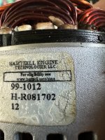
So, let the autopsy begin; Plane Power AL12EI60, s/n H-R081202, no external damage noted. A black dust/power is visible in all of the vent holes.
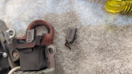
I removed the rear cover and observed that the rectifier was blown apart and literally hanging by a (brass) thread. Scorching, burn marks, and discoloration of the top diode carrier plate.


The top plate, which holds the 4 "negative" diodes showed evidence of overtemperature and all 4 diodes were failed, some open, some shorted. The bottom plate, which holds the "positive" diodes, was in better shape, but only 2 of the 4 diodes tested "Ok". Clearly a failed rectifier -- but why?
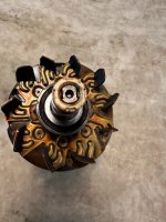
Splitting the case and removing the rotor revealed more ugliness - this alternator was clearly on its way to a total meltdown. The varnish on the magnet wire in the stator and on the fans of the rotor was discolored. The rotor showed signs of dragging the lam-stack of the stator. For reference, the O.D. of the rotor is 76.4mm, and the I.D. of the lam-stack in the stator is ~77.1mm.


Both bearings rotated easily, and demonstrated no appreciable radial or axial movement of the inner races. The rear bearing was covered in black dust/powder and the outer race surface showed evidence of wear/movement.
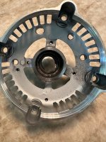
The rotor was clearly wobbling, and dragging on the inside of the stator. Wear marks are evident and more prevalent on the aft portions of the prawls. This indicates that the rear bearing is moving radially in its retention cavity (SRE).
The rotor assembly, bearing and all, dropped out when I flipped the SRE assembly over. The cavity provided almost zero interference retention with the bearing.

Failure Root Cause:
The SRE bearing had "spun" in its housing over time for unknown reasons. On the incident flight, enough material had worn away to allow the rotor to oscillate (wobble) radially, and interfere with the stator. This interference produced a tremendous amount of heat (friction), which began to 1.) melt the varnish of the stator windings magnet wire, 2.) overheat the rectifier, diodes, causing them to fail. Once a plurality of diodes failed, the alternator was no longer producing DC voltage and the overvoltage/crowbar circuit tripped which shut down the field current. A blast tube was installed to direct air at the regulator heatsink, no failures observed in the regulator.
Commentary:
We assume a great deal of risk when we fly, and we rely on our suppliers to do "the right thing" with the products that we use. This SRE bearing/cavity issue has been around "for awhile now" (@DanH, @BillL for details/dates) but I don't recall seeing an SB or similar from anyone at Van's or Hartzell regarding it or any communication regarding next steps ( the minimum thing, the right thing would be to replace/rework the SRE, bearing and rotor.)
If this wasn't experimental aviation, and the FAA/NTSB "knew" about this failure mode, and/or there was an accident caused by this failure mode, I suspect the fleet would have been grounded by now.
This failure mode concerns me (...scares the he77 out of me, actually...). I think I may replace that SRE bearing with a larger (taller) one -- there's room in the SRE cavity (~13mm) for it.
-Brian-
I received the following unit from our comrade Brian Beatty (@bdbeatty) today. This alternator failed enroute to OshKosh a couple of years ago, after only a few hundred hours. Initial analysis by Hartzell/Plane Power was insufficient - stopping at the first thing that they saw and then denying his warranty claim because he had previously removed the rear cover to have a look.
...Boo Hartzell, Boo...
Findings:
So, let the autopsy begin; Plane Power AL12EI60, s/n H-R081202, no external damage noted. A black dust/power is visible in all of the vent holes.
I removed the rear cover and observed that the rectifier was blown apart and literally hanging by a (brass) thread. Scorching, burn marks, and discoloration of the top diode carrier plate.
The top plate, which holds the 4 "negative" diodes showed evidence of overtemperature and all 4 diodes were failed, some open, some shorted. The bottom plate, which holds the "positive" diodes, was in better shape, but only 2 of the 4 diodes tested "Ok". Clearly a failed rectifier -- but why?
Splitting the case and removing the rotor revealed more ugliness - this alternator was clearly on its way to a total meltdown. The varnish on the magnet wire in the stator and on the fans of the rotor was discolored. The rotor showed signs of dragging the lam-stack of the stator. For reference, the O.D. of the rotor is 76.4mm, and the I.D. of the lam-stack in the stator is ~77.1mm.
Both bearings rotated easily, and demonstrated no appreciable radial or axial movement of the inner races. The rear bearing was covered in black dust/powder and the outer race surface showed evidence of wear/movement.
The rotor was clearly wobbling, and dragging on the inside of the stator. Wear marks are evident and more prevalent on the aft portions of the prawls. This indicates that the rear bearing is moving radially in its retention cavity (SRE).
The rotor assembly, bearing and all, dropped out when I flipped the SRE assembly over. The cavity provided almost zero interference retention with the bearing.
Failure Root Cause:
The SRE bearing had "spun" in its housing over time for unknown reasons. On the incident flight, enough material had worn away to allow the rotor to oscillate (wobble) radially, and interfere with the stator. This interference produced a tremendous amount of heat (friction), which began to 1.) melt the varnish of the stator windings magnet wire, 2.) overheat the rectifier, diodes, causing them to fail. Once a plurality of diodes failed, the alternator was no longer producing DC voltage and the overvoltage/crowbar circuit tripped which shut down the field current. A blast tube was installed to direct air at the regulator heatsink, no failures observed in the regulator.
Commentary:
We assume a great deal of risk when we fly, and we rely on our suppliers to do "the right thing" with the products that we use. This SRE bearing/cavity issue has been around "for awhile now" (@DanH, @BillL for details/dates) but I don't recall seeing an SB or similar from anyone at Van's or Hartzell regarding it or any communication regarding next steps ( the minimum thing, the right thing would be to replace/rework the SRE, bearing and rotor.)
If this wasn't experimental aviation, and the FAA/NTSB "knew" about this failure mode, and/or there was an accident caused by this failure mode, I suspect the fleet would have been grounded by now.
This failure mode concerns me (...scares the he77 out of me, actually...). I think I may replace that SRE bearing with a larger (taller) one -- there's room in the SRE cavity (~13mm) for it.
-Brian-