

Van's Air Force

The definitive Van's Aircraft support community! Buying, building or flying an RV? Join our exclusive family of mentors and enthusiasts!

Plane Power Alternator Cooling Manifold

Ron Earp

Member
Patron
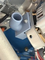
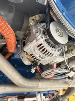
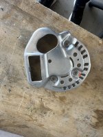
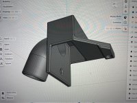
I was looking for a solution to get a blast tube mounted to my Plane Power alternator for cooling. There was some sort of 3D manifold available at some point but the website for it seems defunct. Therefore, I spent a couple of lunch hours to design one and do some test prints.

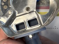
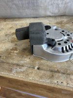
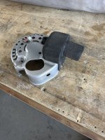
This is what I have so far and it seems to work fine for mounting. It uses one existing hole on the back of the alternator and requires one hole to be drilled in the side of the sheet metal aluminum cover. Has a tiny bit of gap on the side right angle junction but I think I’ll just fill that with silicone. I might clock the inlet up 20 degrees or so, but overall I think this will work.

Next steps will be to print from PA-6 GF which should be good to 360 a 414F. I think the final part I’ll print from that and also put IR reflective foil on it. That should be good I think. Might do some rounding and a support beam on the inlet but it’s already 3.5mm thick. Reckon I’ll print a working prototype and subject it to some heated stress tests.
 

Attachments

  • IMG_0673.jpeg
    IMG_0673.jpeg
    6.9 MB · Views: 59
  • IMG_0717.jpeg
    IMG_0717.jpeg
    1.6 MB · Views: 57
  • IMG_0716.jpeg
    IMG_0716.jpeg
    2.4 MB · Views: 58
  • IMG_0721.jpeg
    IMG_0721.jpeg
    2.4 MB · Views: 59
Good idea, nice design. The challenge will be to stop the soft aluminum cover from cracking. They already do, with nothing hanging on them.

Any thought about simply printing a one piece cover with the hose spigot ?
 
1. Enlarge the holes in the rear cover over the heat sink
2. Add an aluminum bushing in the hold down arm, and put some kind of lock washer on this screw. The screws on the back are critical electrical connections to & through the rectifier bridge.
3. Use an MS21042 or 43 nut on the single screw that holds the apron to the side of the rear cover.

Here's mine:

IMG_6979.jpegIMG_6977.jpegIMG_6978.jpeg
 
Some good ideas for changes. On this design I didn’t use any of the alternator bolts that were already present. It uses a an unused hole in the back cover to mount and you add one on the side. These screws and nuts are for mock up only. I’ll use metal lock nuts on any hardware if I put this into use.

Me designing a one piece cover probably isn’t in the cards. I suck at CAD work and this is probably about all I can muster. It’s a good idea though!
 
Some good ideas for changes. On this design I didn’t use any of the alternator bolts that were already present. It uses a an unused hole in the back cover to mount and you add one on the side. These screws and nuts are for mock up only. I’ll use metal lock nuts on any hardware if I put this into use.

Me designing a one piece cover probably isn’t in the cards. I suck at CAD work and this is probably about all I can muster. It’s a good idea though!
That unused hole is the stator center tap. For peace of mind, I would put a piece of Kapton tape over the screw head.
 
Last edited:
Nice work. My 3D CAD skills are OK. My 3D print skills are less, limited primarily due to not having access to a 3D printer anymore. I have borrowed one. That one part I made came out nice. Had help with Mesh and Slicer conversion. I may take the plunge. I am making my air cooling plenum for alternator out of metal or fiberglass.
 
........Any thought about simply printing a one piece cover with the hose spigot ?
Bad idea if you're thinking plastic. Unless you design it with metal inserts for the screws. Printed metal would be fine.

Remember the nuts or screws which hold the rear cover also clamp the rectifier bridge to ground. If/when the plastic extrudes even a tiny bit, the fasteners lose preload and you end up like that guy a few months ago: https://vansairforce.net/threads/plane-power-alternator-failure-redux-redux.235525/#post-1849224
 
Yikes don’t want that to happen! I’ll need to make sure the screw on the back side I’ve decided to used will be secure and can come loose and hit the stator tap. That would be a bad day. Once I get this sorted to now I’ll use it I’ll upload the print file if anyone wants it.
 
At a minimum, deburr the aluminum cover. Cracks love a notch, no matter how micro.

Second, clean with MEK, then put a little blob of oil-proof silicone sealant anywhere around the perimeter where the alternator case is close to the edge of the sheet metal. (It should be done to any Plane Power, brand new from the box.)
 
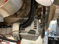
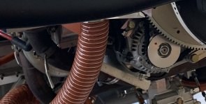
I have a thermocouple bonded to my PP alternator. The combination of a blast tube and, most importantly a heat shield mounted on the #1 exhaust pipe keeps the temperature in check (under 100F).

1784908600175.jpeg

1784908727330.jpeg
 
I have a thermocouple bonded to my PP alternator. The combination of a blast tube and, most importantly a heat shield mounted on the #1 exhaust pipe keeps the temperature in check (under 100F).

View attachment 124097

View attachment 124098
The location of that t-couple is great for measuring the ambient air & DE bracket temps.

However, the heat producers are in the SRE*; the rectifier bridge in particular isn't all that great at sinking heat into the SRE bracket -- It has no heat sink fins like the regulator - it sheds heat through a very few (3 screws, contacts) into the SRE bracket.

Bringing fresh, non-ambient air into the SRE is essential -- good job. Although the corrugated tubing generates a bit of pressure loss along its length. Smooth inner wall SCEET would be best.

* and the Stator and Rotor windings -- current flow in wire produces heat.
 
Last edited:
I have a thermocouple bonded to my PP alternator. The combination of a blast tube and, most importantly a heat shield mounted on the #1 exhaust pipe keeps the temperature in check (under 100F).

View attachment 124097

View attachment 124098
i have the same set up but if I recall correctly the cooling blast tube should be directed at the back of the alternator rather than the front side of that back shroud. I have me cooling blast tube blowing forward into the back vents. I think that is the way the cooling fan works so that my blast assists rather than fights the internal cooling air flow path. You may want to check that.
 
I have a B&C alternator and removed the rear cover to drill a hole for a blast tube, which is attached to the cover with black silicone. I'll try to get a pic next time the lower cowling is off.
 
I have a B&C alternator and removed the rear cover to drill a hole for a blast tube, which is attached to the cover with black silicone. I'll try to get a pic next time the lower cowling is off.
FYI - The B&C (LX60) doesn't have a internal regulator -- It's there, but it's hollowed out/bypassed/and just a carcass along for the ride. All of the heat (well, most of it anyway) comes from the rectifier bridge. Position blast tube accordingly.
 
FYI - The B&C (LX60) doesn't have a internal regulator -- It's there, but it's hollowed out/bypassed/and just a carcass along for the ride. All of the heat (well, most of it anyway) comes from the rectifier bridge. Position blast tube accordingly.
Yes, mine is externally regulated. I was trying to give it blast air for the field windings and possibly bearings, but couldn't figure out where the air is taken in for that exactly. It is likely cooling the rectifier.
 
Back
Top