

I wanted to find a safe way to check the timing of my electronic ignition without being so close to the prop, and without the need for another person.
I made a bracket that would mount in the left inlet and allow an adjustable pointer to be mounted 3" from the back of the prop. I then set the timing that I wanted using the marks on the flywheel and a 32 oz yogurt container mounted to the nose cone with blue masking tape..... It had my cell phone mounted to it with blue masking tape also. With my Clinometer app, I had accuracy to within a 10th of a degree.
I then transferred the timing mark to the back of the prop and adjusted the pointer to alignment viewed from the pilots seat. I set the timing light in position close to the pointer secured to the top of the motor.
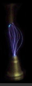
Waited till sunset, jumped in and fired it up..... perfect timing, with and without the vacuum line connected. So how accurate is it..... at that distance from the flywheel, 1/4 inch is one degree of movement.
I made a bracket that would mount in the left inlet and allow an adjustable pointer to be mounted 3" from the back of the prop. I then set the timing that I wanted using the marks on the flywheel and a 32 oz yogurt container mounted to the nose cone with blue masking tape..... It had my cell phone mounted to it with blue masking tape also. With my Clinometer app, I had accuracy to within a 10th of a degree.
I then transferred the timing mark to the back of the prop and adjusted the pointer to alignment viewed from the pilots seat. I set the timing light in position close to the pointer secured to the top of the motor.
Waited till sunset, jumped in and fired it up..... perfect timing, with and without the vacuum line connected. So how accurate is it..... at that distance from the flywheel, 1/4 inch is one degree of movement.
Last edited:


![IMG_20250507_203010802_HDR~2[1].jpg](https://vansairforce.net/data/attachments/65/65687-4ba446e00197ac5fa3ffada6725d7dce.jpg?hash=bGLqBnjCs8 "IMG_20250507_203010802_HDR~2[1].jpg")
