What's new
Van's Air Force

Don't miss anything! Register now for full access to the definitive RV support community.

Lower Baffle: How tightly wrapped?

claycookiemonster

Well Known Member
How tightly should the lower baffle parts be pulled against the bottom of the cylinder cooling fins?
I'm fabbing the threaded rods that pull the lower parts of the baffle around the cylinders, and I can't find any guidance on how tight they should end up. Something tells me they shouldn't actually make contact with the fins, but I've been wrong before. Any specific gap to strive for?
 
The way to go there is to form them (bend them) where they naturally fit tightly and evenly against the cylinders. Then, you use the tie-rods (or your method of choice) to secure them in that position so air pressure doesn't push them outta place. If they are properly formed, the tie-rods don't apply much pressure at all.
 
Tight. The point is to maintain flow all the way to the exit at the fins in the spark plug and CHT sensor vicinity, and not leak out the sides of the wrap.

Tie rods are common, but they directly tie two independently vibrating cylinders, in addition to being in close proximity to (or contact with) the oil drain tubing. Safety wire (0.041") works well, although it does require the addition of a curved flange in a few spots.
.
 

Attachments

  • Baffle Ties.jpg
    Baffle Ties.jpg
    152.6 KB · Views: 456
  • P1100001.JPG
    P1100001.JPG
    67.1 KB · Views: 446
  • P1100002.JPG
    P1100002.JPG
    81.8 KB · Views: 404
  • P1100003.JPG
    P1100003.JPG
    76.6 KB · Views: 420
  • Extension.jpg
    Extension.jpg
    63.2 KB · Views: 381
Impregnated fiberglass

A wrap of Ultra Black RTV impregnated fiberglass around the cylinder fins helps keep the baffle from leaking and they don't have to be quite as tight. I marked where the baffles cover the fins and applied the fiberglass to those areas.
 
Last edited:
Tight. The point is to maintain flow all the way to the exit at the fins in the spark plug and CHT sensor vicinity, and not leak out the sides of the wrap.

Tie rods are common, but they directly tie two independently vibrating cylinders, in addition to being in close proximity to (or contact with) the oil drain tubing. Safety wire (0.041") works well, although it does require the addition of a curved flange in a few spots.
.

Like Dan says - otherwise the cylinder fins will wear right through your baffles. Using safety wire is a good idea too.
 
A wrap of Ultra Black RTV impregnated fiberglass around the cylinder fins helps keep the baffle from leaking and they don't have to be quite as tight.

They kinda do, although gasketing seems to help with wear as well as leakage.
.
 
I cut the thin baffling material supplied by vans to fit, then contact cement to the baffle. I tighten up to seal the material against the cylinder fins. This not only seals to direct airflow through the fins, it also protects against the cylinder fins wearing through the aluminum baffle due to vibration. I also use a small compression spring on the baffle tie that allows a bit of expansion/contraction of the cylinders while still maintaining tension of the baffle.
 
Last edited:
I'm seeing some silicone/glass wraps which appear pretty rough. Here's the technique...

Lay out some 4 or 6 mil (i.e. heavy duty) plastic sheet. Lay a ply of 9 oz plain weave fabric, then squirt Permatex Ultra Black (aka Loctite 598) on the fabric. Lay another sheet of plastic on top. Now roll back and forth over the sandwich with a rolling pin, chunk of pipe, whatever you have, working the silicone down through the fabric. Flip the sheet to see how you're doing; it's clear plastic sheet, right?

When the fabric is fully saturated, roll hard to work excess silicone out to the perimeter of the sandwich, off the glass.

Clean the edges of the fins with MEK or acetone. Measure the exact size of the fin area to be covered. Draw the shape, exact size, right on the top plastic sheet. Cut the shape with your shop scissors, the end result being a plastic/glass/plastic sandwich which exactly fits where you want it. It's not sticky or messy, so hold it in place to check fit. Not perfect? No problem, trim to suit.

When the fit is good, peel the plastic off the side which will stick to the fins and smooth it into place. Leave the plastic sheet in place on the outside until the silicone cures a day or two, then peel it off. The result will be neat and smooth, with no strings or blobs.

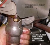
Don't want air sneaking between the silicone/glass wrap and the aluminum wrap. If they are not pressed firmly together, a tiny bead of sealant will block the path.
.
 

Attachments

  • P1250001.JPG
    P1250001.JPG
    239.8 KB · Views: 339
  • P1250003.JPG
    P1250003.JPG
    226.9 KB · Views: 303
  • Cylinder Wrap Sealing.jpg
    Cylinder Wrap Sealing.jpg
    22.1 KB · Views: 247
Last edited:
Howdy everyone. I am ready to wrap the baffles around the cylinder fins. I like Dan H's idea, but it is not clear to me how the safety wire is twisted to draw the aluminum tight against the fins. I don't understand how to twist the wire, draw the baffles tight to the fins and then secure it in place all together.

I have also seen people use short pieces of welding rod at the ends of the safety wire to span the width of the baffle flange. Again, not sure how to install these rods and twist/draw the baffles to the fins and secure.

Much obliged.
 

Attachments

  • Capture.PNG
    Capture.PNG
    252.3 KB · Views: 105
Last edited:
Mike, you hand form the baffles to be tight. The wire just keeps the pressure differential from spreading the lower baffles in flight.

You use safety wire pliers to twist the wires.
 
Thanks Kyle. I have been building this plane for 6 years come December; I never thought about bending the baffles to fit first, then wire to hold in place! Funny how the mind works...and doesn't!
 
A quick question.

I ran the seal all the way up behind the airdam on the front cylinder, BUT I am suspecting that I ran it too far up ? Should I have stopped at the blue line ?
[It is very easy to trim up as it is still damp/soft]

One thing to note is there ARE cooling fin behind all the of seal an air CAN pass from top to bottom. This is not true on all cylinder types, but here there certianly is a 1/4inch of air flow at the narrowest point towards the top of the cylinderhead.

Thanks


Baffle seal.jpeg
 
Last edited:
When I was installing the baffle, I had problems with creating the threaded rod so I used the safety wire technique. But I found out that didn't create a lot of tension to seal the lower baffle.

I then discovered that McMaster-Carr sells the 6-32 threaded rod. I found out this threaded rod really pulls in the baffle. Note, I covered the lower thread portion of the rod with poly tubing to keep it from rubbing against the engine.

 
David, it is not too tight in general but that head section at the casting parting line has nearly zero fin depth and needs an open pocket below the center line. Having sealed on and above the centerline line is a little problematic as the baffling angle that is structural for the inner wraps fits tight against the head. Even of wrap stops below the CL, you can use hight temperature 3M HVAC tape to adjust the flow to restrict the front and allow more flow to the rear cylinders. I consider that necessary for tuning in phase . The opening to the lower fins goes for the back side of #3 . My theory is plenty of air will go through the fins, but the total flow is too easily limited at the bottom exit slot. I used the Sam James slot dimensions and believe that is how he restricted flow. DanH idea of pressurizing the lower plenum (downstream of the fins) to restrict/manage total flow allows a cowl flap to limit at high speeds and yet low restriction across the engine for full power climbs on a hot day. I do believe that the barrels can tolerate wraps up to the centerline down to the intersection baffles.

If you look here there is a template for the aft chute, but you will have to be creative for a chute on #2. My 10 friend found this out after building . He had high relative #2 temps. We drilled 4 #30 holes to match the fin gaps and lowered the temp 10F. The holes were at about 45 deg into the baffle angle bend. We were surprised that little air made so much difference.
 

Attachments

  • IMG_6027 #2 cylinder cooling.jpg
    IMG_6027 #2 cylinder cooling.jpg
    2.6 MB · Views: 12
  • RR_Baffle_Template v2.pdf
    255.9 KB · Views: 10
Last edited:
Back
Top