What's new
Van's Air Force

Don't miss anything! Register now for full access to the definitive RV support community.

Hartzel CS Prop Vans Spinner

wirejock

Well Known Member
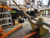
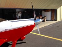
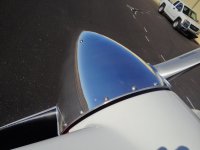
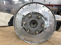
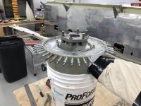
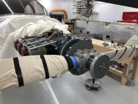
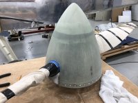
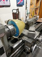
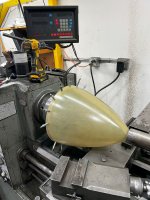
Anyone have tips or tricks for fitting a Vans Spinner to a Hartzel CS prop?
-The big cutouts?
-The nutplates? I did find a couple threads.
-Gotchas?

Mine is not gel coated. Thank goodness. Hate that stuff. I should be able to target wirh a strong light.

The manual is fine and I plan to follow it but the "collective" always seems to find a better way to build the proverbial mousetrap.
 
Hartzell has a template for cutting the Van's spinner with the correct holes for their prop. Check their website. If you can't find it, PM me and i can email what was sent to me.
 
Here is one way to check the cut outs at high pitch. The engine hoist is used to hold the blade against the springs in the prop while you mark the clearance. The spinner was checked for wobble on the bench by mounting it on a lazy susan and using a dial indicator attached to the arm of the engine hoist. This allows you to reach over the prop so you can turn it 360 degrees.
Stewart Willoughby, 6
 

Attachments

  • 20220522_211033.jpg
    20220522_211033.jpg
    406.8 KB · Views: 149
No sweat

Larry,

I fitted mine last year, no issues just by following the directions.

I fab’d a couple of paddles from 2x4’s, held by “C” clamps, to facilitate rotating the blades thru full travel. I just trimmed profiles in the studs to match the chord profile of the blades fairly near the hub. Moved these using the Armstrong method, not too tough. Then I simply trimmed the spinner cutouts accordingly.

Yep, a small flashlight worked well for hole locations.

PIREP on the spinner: no issues, everything performs as expected. Had my combo balanced in Akron and it all feels nice and smooth in flight.
I’m at 18V, and get to the chow wagon in Longmont occasionally. Stop by for a peek if you like.

Have fun…
Jim
 
Make sure the blades have plenty of clearance, I have a trashed set of blades sitting here due to blade root wear from spinner.
 
There is a "no holes" approach you might choose to go with - all the screws behind the rear mounting plate instead of around the circumference of the spinner.
 
There is a "no holes" approach you might choose to go with - all the screws behind the rear mounting plate instead of around the circumference of the spinner.

I did that...the "screwless spinner"...and love it! I'll look for some pics of it...
 

Attachments

  • IMG_1201.jpg
    IMG_1201.jpg
    418.2 KB · Views: 115
  • IMG_1202.jpg
    IMG_1202.jpg
    330.3 KB · Views: 122
  • IMG_1208.jpg
    IMG_1208.jpg
    283.4 KB · Views: 111
  • IMG_5579.jpg
    IMG_5579.jpg
    391.8 KB · Views: 125
  • 58484364975__F8E97FAF-CCF4-4DBC-A97B-8B2065E3DC18.jpg
    58484364975__F8E97FAF-CCF4-4DBC-A97B-8B2065E3DC18.jpg
    425.5 KB · Views: 132
Pictures

Thanks Bill. Photos worth many words.
For some reason, I thought it had to be done with the prop secured in place. That bucket thing is neat.
Any tips on cutting the big holes.
 
Thanks Bill. Photos worth many words.
For some reason, I thought it had to be done with the prop secured in place. That bucket thing is neat.
Any tips on cutting the big holes.

You can do most of the work after you've mounted the prop and gotten the spinner properly centered (and thus clecoed in place), and then remove the prop and work on just the backplate and spinner alone. I also did the proseal on the forward bulkhead, but I honestly don't think it would have made much difference...there's almost nothing there after I laid it up.

ETA: Do a search "screwless spinner". https://mstewart.net/super8/spinner/index.htm

But there ARE some caveats that aren't captured in all the sites that mention it...things like ensuring you have compete fill of fiberglass, epoxy and flox so the flange doesn't have a spot to start separating from the spinner, etc. The original write-up on this wisely said "don't do this if you aren't VERY sure of your fiberglass skills" or words to that effect.

Still...it's not a *hard* job, just a little time-consuming...but boy, does it ever look pretty!
 
Last edited:
Good method for keeping it true

In order to keep the spinner and bulkhead true with one another, I chucked the bulkhead up in the lathe one evening after work. I then gently pressed the tailstock over the nose of the spinner to center it up relative to the bulkhead.

I pre-sharpied all my index points for screws on the bulkhead, and could easily see them through the spinner.

5 minutes and I had all the screw holes drilled, and a spinner that was true as could be! Once assembled onto the prop, the forward bulkhead was self-aligning, and easy to drill.


This probably would have been easier before I routed out the cutout for the constant speed prop, but I did still manage to find 3 points of contact for the chuck jaws by clocking the doubler plate one set of rivet holes out and cleco'ing it in place.
 

Attachments

  • spinner.jpg
    spinner.jpg
    489.7 KB · Views: 110
  • spinner drilled.jpg
    spinner drilled.jpg
    505.7 KB · Views: 111
I found the spinner pretty easy to fit. I remember scribe lines on mine that showed the initial cut, but then I had to open it up more to have clearance. The scrap was not adequate to make the cover plates, but 4 layers of 9-oz laid up on the spinner itself as a form (plastic covered)and voila - plenty of properly shaped material to make the cover plates.

Those Cummings spinners are quite nice though. But it's time v. money. The fiberglass spinner is easy enough and much lighter.

I've had my prop overhauled, and after that the forward flange was off and I had to redrill holes in it and move nut plates. I really like this screwless spinner because an overhaul is no big deal.
 
Last edited:
Good Method for Keeping It True -

I'm too dense to understand exactly how you "chucked" up the spinner backing plate - a little enlightenment please.

Thank you - a wonderful idea I will pursue if I can understand the basics.

HFS
 
I'm too dense to understand exactly how you "chucked" up the spinner backing plate - a little enlightenment please.

Thank you - a wonderful idea I will pursue if I can understand the basics.

HFS

The jaws on this lathe chuck are reversible. This means they can clamp from the inside of a ring or bore, or in this case, the center hole in the spinner. While gently tightening it, I made sure to tap the face of the spinner flat against the chuck with a mallet.
 
This being my first time. To move the blades is it just force from the paddles? does pressure need to be released from anything first?
 
Using the Vans Spinner . . .

I was not willing to brave the twisting of the blades with levers, I made an adapter for the governor pad and used air pressure. it moves pretty easy that way. 25-30 psi IIRC. And can select an intermediate point with a regulator.

I used the Hartzell supplied opening, but recall it was not perfect and enlarged it at full coarse pitch. Larry, in the next few days I could put a piece of paper on mine and trace it for you as a beginning.

I did this as well. V straight forward. Removes all doubt.

https://share.icloud.com/photos/0e9IpKeqHlwd-VvgAkCmfGKBw
 
Any tips on cutting the big holes.


Larry,

An everyday holesaw made pretty clean holes for me. Cut undersize just big enough to fit over the blades, use cutoff wheel to cut from the rear of the spinner to the holes, mount with side clamps (the spinner will stretch over the gap fillers), adjust for zero runout, drill a few holes, cleco, fit to the gap fillers, and refine blade clearance.
 
Tracing

I was not willing to brave the twisting of the blades with levers, I made an adapter for the governor pad and used air pressure. it moves pretty easy that way. 25-30 psi IIRC. And can select an intermediate point with a regulator.

I used the Hartzell supplied opening, but recall it was not perfect and enlarged it at full coarse pitch. Larry, in the next few days I could put a piece of paper on mine and trace it for you as a beginning.

That would be awesome. Thanks.
 
Spinner

+1 on the Cummins spinner. I put one on my first 14 build 5 years ago and it was perfect. They were very slow to respond and deliver back then but was worth the wait. I don’t like the look of the screws in the Vans supplied spinner forward bulkhead but I read here that there is a way to do it with only aft bulkhead screws so maybe I’ll try this and save $1400.

Greg
141283, waiting….waiting….
 
Last edited:
Back
Top