
Van's Air Force
You are using an out of date browser. It may not display this or other websites correctly.
You should upgrade or use an alternative browser.
You should upgrade or use an alternative browser.
Garmin GTP59 OAT sensor specs
- Thread starter pravx
- Start date

GTP 59 Spec
Hi Michael,
The GTP59 measures 500 ohm at 0 Degrees Celcius.
Thanks,
Justin
manual says it's RTD. does anybody know - is it Pt100 or Pt1000 ? or can measure it for me ?
thank you
Michael Ivey
Cabin John, MD
Hi Michael,
The GTP59 measures 500 ohm at 0 Degrees Celcius.
Thanks,
Justin
ColoradoSolar
Well Known Member
Untainted123
Well Known Member
When I made my DIY GTP59 I used this sensor from Mouser.com and it has been working great for a couple of years.
ColoradoSolar, any chance you could give me some guidance here. I bought 2 of the 223-1820-ND (SENSOR RTD 1KOHM 0.001% 2SIP) expecting to wire them together to give 500ohm, but I wasn't sure how you mounted it. I thought maybe I could drill out a bolt to make it hollow and mount them inside (they are pretty tiny), then mount the bolt somewhere. This is another project on my todo list I haven't gotten around to. I have the GAD13 ready and waiting, just needed to figure this part out.
ColoradoSolar
Well Known Member
ColoradoSolar, any chance you could give me some guidance here. I bought 2 of the 223-1820-ND (SENSOR RTD 1KOHM 0.001% 2SIP) expecting to wire them together to give 500ohm, but I wasn't sure how you mounted it. I thought maybe I could drill out a bolt to make it hollow and mount them inside (they are pretty tiny), then mount the bolt somewhere. This is another project on my todo list I haven't gotten around to. I have the GAD13 ready and waiting, just needed to figure this part out.
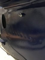
I don't have any pictures of the process of making the mount but I basically did what you described, except that I didn't use a bolt. I used a piece of aluminum rod cut some threads on the outside, drilled a hole in the middle and mounted the sensor in the hole with some silicone. I drilled all the way through and put the end of the sensor flush with the end of the "bolt", I figured it would react faster that way. I have attached the one picture I have of it mounted.
Attachments
Untainted123
Well Known Member
Thanks for the confirmation of my idea. Did you wire it with the 3 wire back to the GAD13 using a shielded 22awg? Is it ok with that long of a run from the probe to the GAD, or is your GAD back there too?
I kind of get lost about which exact wires go where: the RTD I bought only has 2 leads (makes sense since it's a resistor), but I need 2 of them in parallel to bring the 1k down to 500ohm, and then just solder 2 wires on one lead, and a single wire on the other?
From there, my understanding is that the shield be grounded at the base of the probe, against the skin, and then 2 of the wires to one side of the RTD, soldered or attached however, then the other wire to the other side of the RTD, then all that back to the GAD13.
Then the 2 wires that are hooked to the same side of the RTD going to Pin 3 and 6 of the GAD13 and the single one going to Pin 8? Another poster seemed to indicate that 3 wires were optional, but would improve the accuracy, and 3 wire shield 22awg is easy enough anyway.
ColoradoSolar
Well Known Member
Thanks for the confirmation of my idea. Did you wire it with the 3 wire back to the GAD13 using a shielded 22awg? Is it ok with that long of a run from the probe to the GAD, or is your GAD back there too?
I kind of get lost about which exact wires go where: the RTD I bought only has 2 leads (makes sense since it's a resistor), but I need 2 of them in parallel to bring the 1k down to 500ohm, and then just solder 2 wires on one lead, and a single wire on the other?
From there, my understanding is that the shield be grounded at the base of the probe, against the skin, and then 2 of the wires to one side of the RTD, soldered or attached however, then the other wire to the other side of the RTD, then all that back to the GAD13.
Then the 2 wires that are hooked to the same side of the RTD going to Pin 3 and 6 of the GAD13 and the single one going to Pin 8? Another poster seemed to indicate that 3 wires were optional, but would improve the accuracy, and 3 wire shield 22awg is easy enough anyway.
It's been a couple of years so my memory is fuzzy but let me see if I can provide some answers.
- I did install the GAD13 in the tail because I would rather have a longer canbus than the wires from the sensor.
- I did use shielded wire but I don't remember if I grounded the shield at the sensor or just at the GAD13.
- 3 wires are optional but they can provide a better reading especially if the wire run is longer. The reason is that you can get some voltage drop on the power wire (pin 8) and having a separate sense wire you can get the actual voltage the sensor is seeing instead of the voltage at the GAD13. The sense wires are super low (basically 0) current so little to no voltage drop from the wire. I think 3 & 8 should be connected to the same pin on the sensor and 6 goes to the other pin. You definitely don't want to connect 3 & 6 together.
Untainted123
Well Known Member
- 3 wires are optional but they can provide a better reading especially if the wire run is longer. The reason is that you can get some voltage drop on the power wire (pin 8) and having a separate sense wire you can get the actual voltage the sensor is seeing instead of the voltage at the GAD13. The sense wires are super low (basically 0) current so little to no voltage drop from the wire. I think 3 & 8 should be connected to the same pin on the sensor and 6 goes to the other pin. You definitely don't want to connect 3 & 6 together.
Thanks for the info, this helps a lot. I think I get what they are doing now: Power from the GAD13 to the probe (pin 8), a separate wire connected at the probe end together with the wire from pin 8 (pin 3), and the return wire from the other side of the RTD (pin 6).
One last question: is there any polarity on the RTD itself? Or will it work no matter which side I choose for the pin 8 connection?
I finished up my other little project (or least got the plane back together, still need to fly once the WX clears), and will hopefully get to this one soon.
Thanks for the confirmation of my idea. Did you wire it with the 3 wire back to the GAD13 using a shielded 22awg? Is it ok with that long of a run from the probe to the GAD, or is your GAD back there too?
I kind of get lost about which exact wires go where: the RTD I bought only has 2 leads (makes sense since it's a resistor), but I need 2 of them in parallel to bring the 1k down to 500ohm, and then just solder 2 wires on one lead, and a single wire on the other?
From there, my understanding is that the shield be grounded at the base of the probe, against the skin, and then 2 of the wires to one side of the RTD, soldered or attached however, then the other wire to the other side of the RTD, then all that back to the GAD13.
Then the 2 wires that are hooked to the same side of the RTD going to Pin 3 and 6 of the GAD13 and the single one going to Pin 8? Another poster seemed to indicate that 3 wires were optional, but would improve the accuracy, and 3 wire shield 22awg is easy enough anyway.
three condcutor wire is the norm for RTDs. I believe that the negative gets one conductor and the positive gets the doubled conductor.
Larry
ColoradoSolar
Well Known Member
Thanks for the info, this helps a lot. I think I get what they are doing now: Power from the GAD13 to the probe (pin 8), a separate wire connected at the probe end together with the wire from pin 8 (pin 3), and the return wire from the other side of the RTD (pin 6).
One last question: is there any polarity on the RTD itself? Or will it work no matter which side I choose for the pin 8 connection?
I finished up my other little project (or least got the plane back together, still need to fly once the WX clears), and will hopefully get to this one soon.
Makes no difference, an RTD is basically a resistor so you can connect to it either way. Just keep the power wire with the + sense wire and you will be fine.

