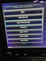
So I did some more troubleshooting today. I guess I was a bit confused on what probe was changed when. I looked at some old pictures and the original probe and harness prior to the panel upgrade were indeed replaced during the panel upgrade. However, I'm not entirely sure what p/n probe was put in during the panel upgrade. The newly installed probe that I was having difficulty with was either discarded or put into a removed parts bin somewhere. In any case, I think I have either the wrong probe or the wrong harness/wiring type. I'll get to that in a minute.
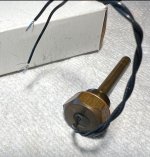
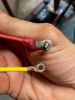
The Molex connector is not the issue. Today I measured the resistance across the connector and there is zero resistance across the connector. The crimps on the sockets and pins looked real good. I once again measured the resistance from the sockets in the J243 connector to the sockets in the Molex connector. The yellow wire associated with pin 33 measured 2.5 ohms and the red wire associated with pin 32 measured 0.8 ohms. I think I have the wrong wiring for the type of probe I have. I have probe p/n 494-70004-00. This is the probe specified in the EIS kit. The installation manual specifies a twisted shielded pair, MIL-C-27500. The harness I have, has red and yellow insulated wires with an exterior braided metal shield, eerily similar to the harness provided with the probe p/n 494-70009-00. That looks like thermocouple type wire. See pictures below. I added clear heat shrink over the red and yellow braided fabric insulation as it was beginning to fray from being manipulated.
View attachment 79836
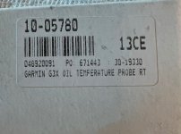
This is the probe I have, p/n 494-70004-00:
Sensor, RTD, Oil Temp (5/8-18 UNF-3A)

sarasotaavionics.com
The harness looks like the one pictured here for p/n 494-70009-00:
Sensor, RTD, Oil Temp
sarasotaavionics.com
So what do you guys think? I don't think I should have a thermocouple type harness with my current probe. Do you think the avionics shop may have originally installed the 70009 probe with that harness and then when the probe started acting up, it was replaced with the 70004 probe?
Thank you!
Jerry