Van's Air Force

The definitive Van's Aircraft support community! Buying, building or flying an RV? Join our exclusive family of mentors and enthusiasts!

EZ-TURN Rotesserie

HFS

Well Known Member
Sponsor
Advertiser
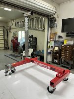
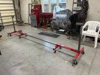
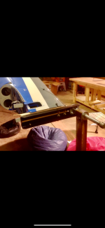
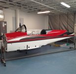
Here are some pics of a rotesserie I made for a friend's -14 fuselage. Started with 2 x 1000 lb engine stands from HF - for all that I cut off/modified, I could have just as easily started from scratch.

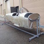
There's a "backbone" that tie them both together, relieving some stress on the fuse.

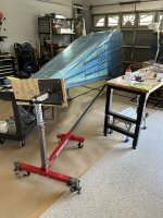
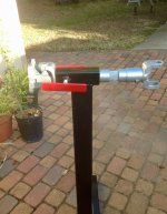
U-joints at both ends insure that fuse doesn't have to be absolutely level when rotating.

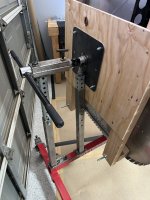
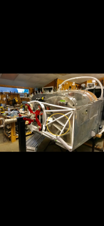
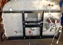
Up/down adjustment for spar carry through clearance at the bottom, or when another operating height is desired.

A split/hinged square tube at the top for convenience of installation. Holes to "pin" fuse at 0 & 90* + 1/2 Allen screw for other settings.

At the head end I added a "Jack" leg to allow for weight build up over time.

4 - 5/8 - 11 adjustable bolts at the corners that lock the stand in place better than wheel locks.

HFS
 

Attachments

  • Rotesserie - RV-14 (1).jpg
    Rotesserie - RV-14 (1).jpg
    1.2 MB · Views: 417
  • Rotesserie - RV-14 (2).jpg
    Rotesserie - RV-14 (2).jpg
    2.4 MB · Views: 407
  • Rotesserie RV-14 (3).jpg
    Rotesserie RV-14 (3).jpg
    2.2 MB · Views: 383
  • Rotesserie RV-14 (4).jpg
    Rotesserie RV-14 (4).jpg
    1.8 MB · Views: 424
Wow, thats really cool David.

I'll be making a rotisserie soon for my project. I'll copy some of your ideas. I didn't really think about tieing the two together.
 
I’m in the same process, thanks for sharing. Q: Why did you offset the tail mounting the way you did? I would think having it centered at the pivot point would make rotating easier.
 
I’m in the same process, thanks for sharing. Q: Why did you offset the tail mounting the way you did? I would think having it centered at the pivot point would make rotating easier.
The fuselage is "level" (and balanced) along the line shown when the forward attach point is 8 3/4" above the bottom of the FW.

We leveled the cockpit longeron, and then "shot" with a surveyor's level a line to the TP - and that's where it came out.

Unless you maintain a straight line (or use a u-joint like I did) between the FW & TP you don't have axial rotation without "loading" up the support tubing running between them.

HFS

More on the clarification of the "axis" of rotation choice -

Given - The FW & TP bulkheads are parallel and square with the top cockpit rail (at least as close as I can determine from the attached Drwg. from Van's). WAG as to the "balance" point on the FW with fuse in "canoe" condition (~8 3/4 to 9"), from bottom of FW. Horizontal line from FW back to TP bulkhead to establish rotation axis for tubing bolted to those bulkheads (perpendicular).

You can see that the rotation axis falls below the TP bulkhead, so an "extension" is required there - hence the 1/2' sheet plywood bolted there. The red line shown is the only axis that the tubes bolted fore & aft are in exact alignment. Arbitrarily, I drew another line (blue) to the midpoint of the TP from same posit on FW - you can see how much the rotating support tubes are now out of line, with some accommodation needing to be made to avoid "stresses" on the FW & TP bulkheads.

Hope this helps about the choices I made ...

OBTW - 9" from bottom of FW works pretty well at this stage of construction.
 

Attachments

  • RV-14 Side View (Rotating Info).jpg
    RV-14 Side View (Rotating Info).jpg
    1.8 MB · Views: 36
Last edited:
The fuselage is "level" (and balanced) along the line shown when the forward attach point is 8 3/4" above the bottom of the FW.

We leveled the cockpit longeron, and then "shot" with a surveyor's level a line to the TP - and that's where it came out.

Unless you maintain a straight line (or use a u-joint like I did) between the FW & TP you don't have axial rotation without "loading" up the support tubing running between them.

HFS
May be I’m not understanding how this has to work (have yet to mount my fuz), but it looks like you have a big offset between the tail mount point of the fusaloge and the point were your plywood mounts to the center of you aft rotisserie support. Just not understanding the need for that.

Hmmm… Looking at it a bit more, I think I understand why you did that. I guess it all depends on how you mount the front. The firewall may need to be a bit out of plum for the tail to be more centered around the rotation point.
 
Last edited:
Wow, thats really cool David.

I'll be making a rotisserie soon for my project. I'll copy some of your ideas. I didn't really think about tieing the two together.
Yes, amazing work!

The connection really makes a difference. There's a lot of forces going on when the fuse is rotated.

Photos of mine. I didn't built it. Someone asked me to evaluate it way back when. Sadly they never went into production. It worked great. I still have it.
20160118_153947.jpg20160118_154052.jpg
 
Last edited:
Could I ask what the 3 pitchforks are for?
Good eyes - those are manure forks modified (by me) to be Cali clamming forks w/sand strainers (barely visible) & clam gauges on the handles …

HFS
 
OK, if we are going to ask about pitchforks, I want to know what Big Mama is?
Big Mama is a 750lb x 30” x 4 1/4” yoke I made w/a 5K squeezer head. On it’s own rolling cart w/ hydraulic jack to raise/lower to work table height. It will dimple (no problem) .063 - 4130 sheet …
HFS
 
Big Mama is a 750lb x 30” x 4 1/4” yoke I made w/a 5K squeezer head. On it’s own rolling cart w/ hydraulic jack to raise/lower to work table height. It will dimple (no problem) .063 - 4130 sheet …
HFS
And I‘ve got “Little Mama” (designed and built by David) in safe keeping - 26” reach - perfect for dimpling/riveting anywhere in a 4’ wide sheet of aluminum! And it only ways 450 lbs……🤣
 
Good eyes - those are manure forks modified (by me) to be Cali clamming forks w/sand strainers (barely visible) & clam gauges on the handles …

HFS
Ha! As a lover of New England clams, I have to say I was never fond or impressed with Pismo clams. Dug my share as a kid. anyway...... ;)
 
Rotisserie: I’ll add a couple more thoughts for people who are going to build a rotisserie.

I used an old drive shaft leftover from a Jeep build after tack welding the bearing cups to the yoke.

Firewall frame is just 1& 1/2” angle iron bolted together and spaced off the firewall with wood plugs cut from a 2x4 with a hole saw. Later went back and doubled up the wood plugs to space the frame further off the firewall. This extra space made room for a lot of firewall work.

After engine mount was installed I fabbed this red fixture out of 1/4” steel plate.

For the aft end I cut 2 spacers out of 3/4” oak and used more 3/4” steel angle bolted to vertical stab attach points. To allow for less than perfect alignment the tail pivot is a 3/4” pipe in a 2” square tube so it’s free to wobble.
 

Attachments

  • IMG_7257.png
    IMG_7257.png
    1.7 MB · Views: 84
  • IMG_7256.png
    IMG_7256.png
    2 MB · Views: 79
  • IMG_7253.jpeg
    IMG_7253.jpeg
    265.4 KB · Views: 80
  • IMG_7251.jpeg
    IMG_7251.jpeg
    554.4 KB · Views: 91
Rotisserie: I’ll add a couple more thoughts for people who are going to build a rotisserie.

I used an old drive shaft leftover from a Jeep build after tack welding the bearing cups to the yoke.

Firewall frame is just 1& 1/2” angle iron bolted together and spaced off the firewall with wood plugs cut from a 2x4 with a hole saw. Later went back and doubled up the wood plugs to space the frame further off the firewall. This extra space made room for a lot of firewall work.

After engine mount was installed I fabbed this red fixture out of 1/4” steel plate.

For the aft end I cut 2 spacers out of 3/4” oak and used more 3/4” steel angle bolted to vertical stab attach points. To allow for less than perfect alignment the tail pivot is a 3/4” pipe in a 2” square tube so it’s free to wobble.
I am curious as to how “balanced” it was rotationally when connected to the MM - looks like it might be a bottom heavy.

Just askin’ …

Thx - HFS
 
I built a rolling rotisserie with some 2” square tube .
 

Attachments

  • IMG_9419.jpeg
    IMG_9419.jpeg
    410.3 KB · Views: 59
  • IMG_9418.jpeg
    IMG_9418.jpeg
    762.5 KB · Views: 59
I am curious as to how “balanced” it was rotationally when connected to the MM - looks like it might be a bottom heavy.

Just askin’ …

Thx - HFS
It’s just a tiny bit bottom heavy by design to counteract when the canopy was on. That helped a little, but it was really top heavy with the canopy on. The red handles are welded to bolts threaded into grade 5 nuts welded on either side of the 2” tube. With those I can apply friction as needed. Didn’t take a lot to hold the fuse in any position which was very handy for painting. Also drilled a couple holes through the tube and driveshaft so I can pin it when needed in a desired position.
 

Attachments

  • IMG_1402.jpeg
    IMG_1402.jpeg
    648.2 KB · Views: 45
Thanks HFS. Just finished putting fuse on the rotisserie, using your FW/TP attachment elevation (red line). Worked perfectly. No tendency to autorotate. Added ratchet straps to the FW attaching to the stand base for extra security.
 
Back
Top