Van's Air Force

The definitive Van's Aircraft support community! Buying, building or flying an RV? Join our exclusive family of mentors and enthusiasts!

Can't get the bolt into the MT Prop Governor P-860-4!

storkeye

Active Member
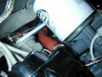
I'm trying to fit the MT P-860-4 prop governor to the engine so I'm following the VA-153 bracket install guide from Vans. All items were supplied by Vans.

I've fitted the bracket and control cable but I can't fit the AN3-11 bolt because it's too long! If I go for a shorter bolt there is not enough shank to include any washers at all. The -11 bolt is just about long enough to include the small washers.

If I rotate the governor arm to full coarse I can just about force a -10 bolt in but not with the VA-153 bracket in place as well. The thickness of the bracket makes it impossible to fit a -11 or -10 bolt. Any shorter bolt won't capture the nut at the other side.

Before I contact Vans and MT, am I missing something obvious? Has anyone else had this issue?

gov1.png

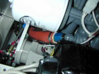
Here is another angle...

gov2.png

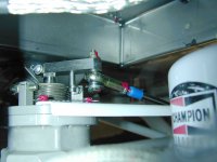
The drawings I have seem to show I have it correct...

gov3.png

Thank you,

Abe
RV-7 IO-360-M1B with Hartzell CS Prop
 
I tried it the other way but the bolt catches on the bracket screw heads when operating the cable. With the bolt as per the plans it seems like the control arm is just a bit too short which is why the bolt won't clear the governor casing.

gov4.png
 
What about temporarily removing the arm?

Whatever you do, don't forget to install that all important jam nut!
 
The control cable needs to be fitted with governor mounted to the engine and the engine mounted to the airframe. So if I remove the arm now, on the bench, it will be really difficult to fit the arm and safety wire it when it's on the engine fitted to the aircraft.
 
It CAN be done without removing arm!, Try rotating arm to extremes of travel. See pic's
Hint: You can get more travel by removing the long screw that is safety wired - leave jamb nut in-place to retain exact position.
 

Attachments

  • DSCE5578.JPG
    DSCE5578.JPG
    110.7 KB · Views: 113
  • DSCE5577.JPG
    DSCE5577.JPG
    94.5 KB · Views: 111
  • DSCE4954.JPG
    DSCE4954.JPG
    101.8 KB · Views: 108
Cut the longer bolt down to whatever length clears the screw heads with the head on the outside. the clean up the threads. If there is not enough thread left to engage the lock portiopn of the nut, use blue loctite instead. DO NOT remove the arm from the governor untill you fully understand exactly what will happen when you do. The main shat will unwind out of position.
 
It CAN be done without removing arm!, Try rotating arm to extremes of travel. See pic's
Hint: You can get more travel by removing the long screw that is safety wired - leave jamb nut in-place to retain exact position.

Great pictures and it looks like my arm is closer to the body than yours. Looking at 3rd picture you have more spline than I do in the same position and using the screw head as a reference, I can see that my arm is closer to the body.

I wonder if I need to bring the arm out a fraction - but not remove the arm from the body or as Larry says it will unwind. Plus the MT manual says not to!
 
I wonder if I need to bring the arm out a fraction - but not remove the arm from the body or as Larry says it will unwind. Plus the MT manual says not to!
I noticed thye same and almost recommended that, but if the arm comes all the way off accidentally you will be having a bad day. Not that hard to cut or grind the bolt shorter. A skill every frabricator should posses anyways.
 
A couple of thoughts:
1. IF you decide to LOOSEN the arm and slide SLIGHTLY outboard, keep in mind some manufactures cut a groove in the splined shaft that keeps the arm on the splined shaft if the bolt becomes loose but stays attached. Work carefully but smartly.
2. I attached the heim joint to the governor without the prop cable attached - it's helpful to know that the prop cable end will spin without issue allowing you to thread it on to the Heim joint later or make adjustments to overall cable length WITHOUT removing the Heim joint. Try it - you may like it.

Added extract from MT manual that shows groove for arm bolt
 

Attachments

Last edited:
Dot punch the inner shaft of the governor and the lever so you can get the lever back onto the shaft in the same position, then remove the lever, install the bolt, install the lever. Tighten the lockscrew and lockwire.

Done.
 
IMO nothing wrong with grinding material off the hex head locally as required down at least as far as the bearing diameter forged under the head.

Note the two 5702-75-60 washers shown in the drawing between the heim bearing and the 5702-475-48 washer. That stack is to prevent the 5702-475-48 washer fouling against the heim bearing. If one, as shown by the OP, works, then OK.
 
Last edited:
I have this same governor on my -14 with an MT prop. The proper sized bolt will not go in without doing something with the arm. Here's how to do it:
  1. Take a good picture of the assembly
  2. Use a fine sharpy and make a mark across the face of the splinned shaft and arm. This is so that if you screw up you know exactly where the arm was.
  3. Remove the safety wire that holds the screw at the end of the arm (closest to the spline)
  4. Remove the screw from the assembly (you can't simply loosen it as there's a grove in the shaft).
  5. Carefully pull the arm toward the end of the shaft as if you were going to remove the arm. Be careful not to pull it to far as you don't want the arm to come off the splined shaft.
  6. When it's far enough out, put the bolt in with the head toward the inside (toward the center of the airplane). If you don't put the nut on the inside, in many installations the bolt will come into contact with the screws that hold the face on when the arm is moved toward the rear of the airplane (depends on how the arm/face is clocked). As shown in your last picture.
  7. Move the arm with the bolt in it back into place. It will only go into one position as there's a slot in the splined arm as stated above.
  8. Reinstall the screw
  9. Safety wire the screw into place with #25 safety wire.
  10. Remember to put a dab of torque seal over the end of the bolt (not the head). This replaces the blue torque seal that was on the the safety wire
It's actually easier to do that to write. Easy? No. Hard, not really...just another one of those jobs that teaches us how to work on an airplane. Obviously if you have a helper it's much easier to do, however I have done it by myself. The governor is a very nice piece of equipment and I've been very happy with it though 150 hours.

If you need additional info, feel free to PM me. Picture below.

Good luck.

Fred

Gov.jpg
 
Last edited:
Rotate the arm/spindle to the "coarse" pitch location. As the arm/spindle rotates - it moves away from the gov. housing.
 
Just to assist with your understanding of these things, here are some (hopefully) helpful points to remember:

While these governors might come set up correctly for your installation right off the bat, you ARE able to adjust them to suit your installation. These particular governors are infinitely adjustable so that you can set them up for your particular engine installation.

The input lever has fine serrations on the input shaft and typically, if you move nothing else, one serration will equal about 100 RPM of change on most governors. Looking at this one in the photo above, I would guess one serration might only give you 75 RPM. That change is either positive or negative, depending which way you move it. If you need to move it for any reason then mark it before undoing the pinch-bolt so you can place the lever back in the same location, avoiding multiple test-runs. In an overhaul shop we normally dot-punch the lever and the shaft as pen ink is lost in the cleaning process.

If you move the lever position on the shaft, you will need to adjust the max/min screw adjustments. They are there to be used, so don't be afraid of adjusting them.

If the angle of your particular input cable on your aircraft doesn't quite align correctly, the screws on the body of the governor can be backed off a little (yes, you will need to cut the lockwire) and the entire centre core of the governor lid can be rotated to realign things where you want it to be. If you adjust the governor in this way without moving anything else (without moving the lever on the serrations and without moving the max/min stops) then nothing in the governor settings will change. All you are doing is moving the top of the governor to a new location to better suit your installation.

While these units will often be set up perfectly when you bolt them onto your engine, remember that these settings are designed to be adjusted and each individual installation could be different, needing small changes. Don't be afraid to make these changes.

So, as per my original post and as per Fred's more detailed post - mark the lever and the shaft (I prefer the dot-punch method as pen marks can be easily lost), remove the lever, install the bolt, refit the lever in the same location. Job done.
 
Last edited:
I tried grinding down the bolt head but my inspector (required in the UK) encouraged me to follow Freds guidance in post #19.

I didn't take the arm off but was able to slide it far enough along the spline to be able to get the bolt in.
 
Just curious, while following this thread I looked at my MT prop governor. In some of the pictures in this thread, and on my governor, the limit screws are installed a bit strangely (to my untrained eye): one is installed with the threaded end of the screw inward and that is what the arm basically hits, the end of the screw. In the other direction, the limit screw is installed so that the arm hits the screw Head. They are both factory installed, safety wired and loc-tighted. You can see what I'm trying to describe in picture number 3 on post 6. The arm stop is bumped up against the screw head.
I guess functionally, they are the same, except that the limit with the screw head can't go any lower than the thickness of the screw head.
Again, just curious, anyone know why they installed the limit screws this way?
 
Back
Top