Sep 12, 2025 -Electrical, Switch, and Panel Design
Last Updated: Sep 21, 2025
SEP 21, 2025: Well, I have already (two days?) made an improvement... I remembered that during the runup (RPM 1700, stick being held aft by the right hand), the PMAGs switches need to be moved to a test position to remove ship's power to verify that the self-generating feature is functioning. So the Mag switches (OFF-TEST-ON) can't be on the right hand. The pictures at the end of the Sep 19, 2025 post have this incorporated, but the tables don't yet. So I'm going to move the Mag switches to the left side.
Latest Sep 2025
SEP 19, 2025: So this post is about 15 years in the making. I spent a lot of time dreaming of how I was going to design the RV-7 panel while I was beginning its build, and when I restarted the RV-8 build (what? a couple weeks ago? The emp kit hasn't even shipped yet), I decided to basically copy my previous thoughts and start from there.
To be honest, the copy-paste method works pretty well, my cockpit design philosophy hasn't changed much since I settled on a design back then, except I've noticed a lean towards simplicity. Anyway, here it goes:
Instrument Panel Philosophy
Glass panel
The first thing to point out is that I am going to have a glass panel airplane. I cannot find a reason to have vacuum powered steam gauges in my panel when the glass panel technology (and reliability) has advanced the way it has at the price point (approaching the same point as steam) it is reaching.
I plan on having one PFD, one MFD (either configurable to a reversionary PFD/MFD mode) and an IFR GPS. The usual host of “radio stack” boxes should be built into the PFD/MFD suite. I’m currently looking at the g3x touch system, and the audio panel, NAV/COMs and Transponders are all remotely mounted.
My emphasis is going to be on a couple of general layout philosophies that will ultimately guide my design.
First philosophy: Switches in Order of Use.
Looking at my proposed before starting checklist, after I’ve done my preflight, briefed my passenger, gotten both of us squeezed into the seats, and I’m ready to start the engine, I’d like to start from one side of the panel, and make sure every switch is in the down position (there will be a few times when this isn’t appropriate but the “down” check should be standard).
Then, first turn on the battery to do last minute voltage checks and engine instrumentation (although I wouldn’t necessarily need this given the backup batteries in the displays…although I’ll have to check if these backups power the engine monitoring system as well), then set power controls, prime, strobes on (+Nav if it’s night), magnetos on, hit starter (or starter-enable switch and stick-mounted starter button), Once the engine has started, check oil pressure, then turn the alternator on (I know I could turn this on before start, but why provide alternator field current when I don’t HAVE to?). After a lot more reading and thought on this, I may decide to turn the alternator on prior to start. More on this later.
Next, I’ll turn on all my radios (I’m going to call this the “Avionics Master” but I’ve read Mr. Nuckoll’s article on the Avionics Master Switch and while I’m convinced I don’t NEED one, but I may WANT one for convenience. I realized I’ll need to convince myself that I’ve eliminated the single-point failure nature of a master switch.)
After the radios are up, get ATIS, clearance, and taxi instructions, time for the taxi light for visibility/recognition on the ground.
Just before takeoff, I’ll flip on the landing lights (maybe wig wag, the name for alternating flashing lights), pitot heat (if IFR) and then the fuel pump for takeoff. Flaps set to takeoff, if required, and now I’m ready for departure.
The above paragraphs are going to drive my switch philosophy, but before we get to my list, let’s talk about the fuel pump more. Is it better to have the fuel pump just right of the main bus switch in preparation for priming? Or perhaps over by the throttle and flap switch, where I will use it for every takeoff, landing, and tank switching operation. I prefer the latter, even though it’s not a perfect match to my “first philosophy.”
In the RV-8 (tailwheel) it is prudent to hold the stick all the way back in your lap for start (although some point out this is unnecessary). So, any switch activations prior to start can be with your right hand on the right side of the panel, but any after start should be accessible with the left hand. Some, may need to be activated quickly with your hand on or near the throttle.
One possible switch layout based on that layout:
- Before Start (Right hand activation before stick-aft for start):
- Battery/Alternator
- Nav Lights
- Strobes
- Starter enable (assuming the starter is on stick grip)
- Magnetos [ed. sep 21, 2025 moving these to LEFT HAND]
- Post Start (left hand)
- Avionics
- Lights (Taxi, Landing, Wig-Wag)
- Pitot Heat
- Fuel Pump
- Flaps (Maybe on the stick)
Great! I’m done with my panel layout!
If only it were that easy. This layout, and basic electrical system, has been used for many years on lots of certified airplanes, but why should I stick with a 50-year-old architecture (but Andrew, why change what works!?) when I am building a brand-new, high-tech, all-glass, airplane?
Bus Architecture
So, let’s come back to the “no vacuum pump” idea. With the IFR flying I’m going to be doing, I’d rather put a back-up alternator on the vacuum pad where the vacuum pump usually sits. These backup alternators are not belt-driven, but gear-driven, and come in a couple of different sizes. 8-Amp and 20-Amp.
So how am I going to hook the backup alternator up electrically? Well, I’ve also read a lot about the endurance/essential/emergency bus idea.
The idea behind an e-bus is that when something bad happens to your main alternator (let’s assume for this discussion you only have one), then you can turn off your battery master (a fast way to “load shed”), and use an e-bus to leave on the items that are really required to continue the flight safely. Whether “continue” means “original destination” or “land when practicable” depends on how long your electrical system can support the load you need for continued safe flight and landing. If you have a good battery AND can load shed enough (if you want this to be part of your emergency actions…some people frown on lots of load shedding actions during an emergency), battery alone may provide enough power that fuel is the limiting factor, and not electrons.
Now let’s introduce a backup alternator. With a backup alternator, you could conceivably load shed below the alternator capacity and continue the flight indefinitely (well, until your fuel runs out).
The nice thing about an e-bus is that it allows quick load-shedding and a dual power path to some “can’t-live-without” goodies in your panel. If you recognize the alternator failure soon enough (annunciations, etc.) then you can load shed via switches or circuit breakers.
So, let’s look at our options for bus architecture.
Option 1: Single Main Bus.
I can hook up the backup alternator with a regulator that only allows it to flow current if the bus falls below a certain voltage (aka, main alternator dies). All equipment is on the main bus (which means if there is a battery contactor failure, I’m “without paddle,” as they say).
Option 2: E-Bus
I could hook up the endurance bus as a true endurance bus; only have the required equipment to continue the flight. The backup alternator could be fed field current from a hot battery bus (or the e-bus) and I could maybe isolate the two busses such that the main alternator is powering the main bus and the backup alternator is powering the endurance bus all the time. A bus-tie contactor could be used to tie the two together so if I have a failure on one, I can save electrons until close to landing, then using bus-tie or the failed side’s master to re-energize that bus for all equipment. One of the AEC drawings has the main bus side always powering the endurance bus through a diode, and then an endurance bus alternate feed for when things start going badly. I really like this idea.
Option 3: Avionics Bus
An older version of this essay introduced an Avionics Bus here, but I am no longer a fan of this. All my engine monitoring is needed for start. Let’s skip Option 3: Option 3: Avionics Bus
Option 4: Avionics bus with endurance bus.
Another Option is to have two buses but also include an emergency bus for each of those buses. Nope, too complicated. (I am drawn to this from my jet and turboprop days, but let’s keep it simple.) Let’s skip Option 4: Avionics bus with endurance bus.
Preflight Checks.
I really like the idea of checking everything on the preflight. On a one-bus system with two alternators, I might turn off each alternator in turn to make sure the other alternator picks up the load. I’m thinking about putting all of my essential items PLUS what’s needed for engine start on the E-BUS. Why?
Because I can climb in the airplane, turn on the e-Bus, and have PFD1, COM1, GPS, EMS, Trims, Fuel Pump, Nav Lts, Strobes, Audio Panel, and the Starter (but nothing else, which means the diode is working).
But there are too many high-draw items there! Well, yes, but also those high draw items are not constant use and could be procedurally prohibited.
Why would I do this? Because I can start the airplane with those, see the aux alt charging the battery, flip on the main bus, and watch the main alt take over and the rest of the boxes power up. Now flip off the e-Bus contactor and make sure everything stays powered. I’ve now checked both alternators, both contactors, and the diode. No additional electrical checks are required. (Side note, on shutdown, stop the engine, then turn off main bus first, see the e-bus equipment stay powered, then turn off the e-bus.
Switch layouts with Option 2
First turn on the e-bus bus, set power controls, prime, magnetos on, strobes on, hit starter. Once started, check oil pressure, main bus on.
Then…lights…blah blah.
Amended switch layout (per first philosophy):
Right Hand (before start)
- E-Bus
- Aux Alt
- Nav & Strobes
- Left Hand (Before Start)
- L Magneto
- R Magneto
- Starter (or Starter enable, guarded or keyed)
Left Hand (after start)
- Main Bus
- Main Alt
- Taxi Light
- Landing Light
- Wig Wag
- Pitot Heat
- Fuel Pump
- Flaps
Yikes, that’s too many switches on the left side, and I don’t like that electrical and lighting switches are separate.
Second Philosophy: Collect, then combine switches were possible and practical
Yikes, those DC power switches sure are physically separated; let’s see what we can do about that…
Should I move the avionics bus /aux alt switch over with the main bus switch and group them as “electrical” or leave it where it is, providing a better flow and better tactile separation? This is a tough one.
I think I’d rather have both bus power switches in the same spot on the right side of the panel.
I don’t want to combine every similar switch possible, but some combinations seem like a good idea. Also, while order of use is importance, I am willing to sacrifice order (a little) to facilitate better groupings of systems. (Bold items have been moved.)
Also, while the Starter Enable Switch could be right hand, I might want to bump the starter in flight. Let’s move it to the left side or on the panel reachable by the left hand.
Right Hand
- E-Bus
- Aux Alternator
- Main Bus
- Main Alt
- Nav Lights
- Strobes
Left Hand
- L Magneto
- R Magneto
- Starter enable (guarded. Maybe on the panel).
- Taxi Light
- Landing Light
- Wig Wag
- Pitot Heat
- Fuel Pump
- Flaps
That’s a little better.
Let’s start some further refinement with the alternators. I’m going to combine the Bus and alternator for each side. 4 functions will now be on 2 switches.
- OFF – MAIN BUS MASTER (this includes the main alternator)
- OFF – E-BUS MASTER (this includes the aux alternator)
Also, I’ll only ever want wig-wag on after I’ve turned on the landing or taxi lights.
- OFF – LDG – WIG-WAG
- OFF – TAXI – WIG-WAG
Also, I think I might be willing to say that I’ll always have the NAV lights on when I turn on the strobes.
With some careful combining and moving (I added grouping labels, too.)
- Main Bus Master
- EBUS Master
- NAV LTS
- STROBE LTS
- Starter enable (or panel)
- L PMAG
- R PMAG
- Taxi Light Wig Wag
- Landing Wig Wag
- Pitot Heat
- Fuel Pump
- Flaps
Back to flow…the nice thing is that on climbout, while transitioning to cruise, I will be using these switches in opposite order. Flaps UP, fuel pump off, pitot heat off (after I’m through the theoretical cloud layer I had to penetrate on takeoff), landing and taxi lights off when transitioning to enroute climb.
Third Philosophy: Tactile feedback
This one is a big one for me and my human factors experience on the turbines. I would like to be able to tell what switch I am grabbing in a dark (or smoke-filled) cockpit. This means that both location and switch type (or feel), along with switch position (up or down…or middle) needs to tell me exactly what that switch does and its current status.
Do I love the perfectly lined up toggle switches that many OEMs use? Of course, but only because it’s aesthetically pleasing.
I’m okay with a group of similar toggles, as long as it is obvious. The easy ones jump out.
Lighting switches will all be regular non-locking toggles with three positions (OFF – NAV – NAV & STROBE, OFF – TAXI – WIGWAG, OFF – LDG – WIGWAG)
Ignition switches will be regular toggles unless I convince myself that the mag switches need to be locking toggles. Not sure on this one yet. Leaning toward locking.
I was thinking of using the red split master switch all the way to the left for the main bus / main alt switch, and a white split master for the avionics bus / aux alt switch in the middle. (If I move the avionics stuff over to the left, I don’t want to use the same switch type, but during the day, one will be red, and one will be white and at night, two split switches next to each other won’t be difficult to navigate given there are only two. Buses on the left side, alternators on the right.) Still undecided on this one, too. I do like those split rockers, but AEC has convinced me to either use DP3T toggles or DP2T, when do I really need to turn off the alt fields?
Let’s take another look at the layout with switch types:
- Main Bus Master (Locking DPDT Toggle)
- EBUS Master (Locking DPDT Toggle)
- NAV LTS (DP2T)
- STROBE LTS (DP2T)
- Starter enable (Covered SPDT toggle)
- L PMAG (DP3T)
- R PMAG (DP3T)
- Taxi Light Wig Wag (DP3T)
- Landing Wig Wag (DP3T)
- Pitot Heat (CB Toggle)
- Fuel Pump (CB Toggle)
- Flaps (ON)-OFF-(ON)
I think this gives me some good separation between similar switch types, and I’ll prevent almost all inadvertent switch operation.
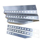
The lights and pitot heat, fuel pump combination is a lot of toggles next to each other, but I think I can mitigate that with actual switch spacing. The RV-8 has an instrument panel, then a couple areas below the instrument panel where some switches could go, see this picture I stole from somewhere see the lower two rectangles?
I've highlighted the areas here that might be worth putting some switches into.
Fourth Philosophy: Normal Operation, switches all up.
The background for this is really a flow check. I want to look down just before takeoff, scan across the panels with either my eyes or my fingers, and have the airplane ready for takeoff with all switches up. (Pitot heat won’t always be needed, but barring any temperature limitations for pitot heat, I won’t be WRONG to have it on for takeoff.)
Okay, we’re done!
Oh wait, what about the “other” switches (Gulp!)
OTHER SWITCHES
Using the above logic and reasoning, I’ve also adding some items to the panel.
These items include:
- Smoke System (with LED indicated “pump on”)
- Copilot stick switches enable
- Interior light dimmers
- Circuit Breakers
- 12V power (maybe USB power, maybe both)
- Eyeball vents
- Cabin heat Knob
- Seat heat switch
The remote setting on the smoke switch will allow a stick-mounted switch to operate smoke. This will be an “enable” switch on the panel, and a push-ON-push-OFF switch on the stick.
The courtesy light dimmer will be on the hot battery bus and will power the footwell and baggage areas. I want to be able to walk up to the plane and turn these on to load baggage and get in the airplane without turning on the master.
Eyeball vent (fresh air), Cabin Heat and Seat Heat for each seat will be on the outer edges of the instrument panel.
STICK-MOUNTED SWITCHES
Looking at Stick switches, I blatantly stole this from Infinity Aerospace: Typical Stick Grip Switch Combinations for Aircraft WITH Electric Flaps AND Autopilot:
(thumb operated 4-way switch via China Hat) — Pitch and Roll Trim
(index finger) — Push-to-talk
(top – thumb side) — Flaps – ON/OFF/(ON) toggle switch using a limit switch on the UP side in series with the Flaps/Speed Brake motor. I may revert here to just a (ON)/OFF/(ON) and get rid of the limit switch.
(half way down, thumb side) — Auto Pilot Disconnect (Normally Open push-button (8632 N.O.))
(pinky switch) — Smoke ON.
(top – knuckle side) — Engine Start Normally Open (8632 N.O.) push-button
Layout:
So where do we put these switches? Originally, I was thinking about a dual-giant-display layout:
This is nice.
I don’t hate this, but it’s expensive and a lot of glass right in front of you. Those switch panels to the left and right are custom, which I am fine with doing.
If I could stick all the “right” switches on the lower right panel, and all the “left” switches on the lower left panel, that would just leave some of the “other” switches (discussed later) on the actual left and right instrument panel edges.
Lower Right:
- Main Bus Master
- E-Bus Master
- Nav
- Strobe
Lower Left:
- L PMAG
- R PMAG
- START Enable
- Fuel Pump
That would leave a ton of space on the actual instrument panel edges for the rest of them:
Upper Left:
- Smoke Enable and On LED
- Pitot Heat
- LDG / Taxi Lts
- Copilot Stick Switches Enable
- Eyeball vent
Upper Right:
- Pilot seat heat
- Dimmers (Instruments, Panel, Courtesy)
- USB power (this may be better in a more hip-proximate place, though)
- Another Eyeball vent
Elsewhere:
- Circuit Breakers (or maybe down low?
- Cabin Heat Push-Pull Knob
- Parking brake Push Pull Knob
But I am absolutely leaning back to two displays. I mean, we are dreaming, right?
Dual screen, switches left, right, and down.