A test exercise
This discussion is all about learning, so I thought I would add a bit to my previous post...
First, a caveat... the results I am presenting are from a simulation that is inexact... but, I am kind of comparing apples to apples, so the relative results tell us something...
I analyzed a few probe mast configurations, using different cross-sections, aspect ratios and Reynolds numbers.
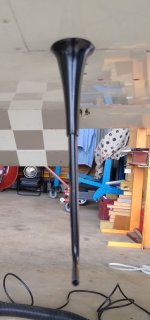
1: A simple tube
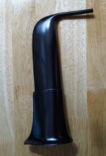
2: Blunt airfoil mast representing what one might make to be robust in the scale we need to make these masts
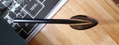
3: A symmetrical laminar section
I ran each model at different Reynolds numbers to 'scale' the model to the appropriate conditions the probe would see on our RVs.... For instance a 1.5 inch chord probe at 150 knots is running at an Re of about 196000. If it was a full scale wing sized object... it would be about 4500000.
Here is an image of each model at Re 200000. Three models have an aspect ratio of 14.5 which would represent a mast of chord ~1.0 inch by ~ 14.5 inches. ( A really long probe) and the other three at AR 7 which would be closer to a real probe to see what difference the AR has on the drag.
The Tube (First image AR 14.5, second AR 7 )


This model had a 3D Cd of 0.0464 at Re 200000
Cd of 0.0341 at Re 200000 AR 7
Cd of 0.0189 at Re 4500000
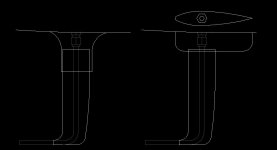
The Blunt foil (again at AR 14.5 and 7)


This model had a 3D Cd of 0.0279 at Re 200000
Cd of 0.0278 at Re 200000 AR7
Cd of 0.0181 at Re 4500000
The symmetric foil


This model had a 3D Cd of 0.0130 at Re 200000
Cd of 0.0133 at Re 200000 AR 7
Cd of 0.0086 at Re 4500000
If you look closely at the cylinder, you see a large 'red' zone at the trailing edge . This indicates stagnated flow over a large area so I REALLY doubt the absolute value of the tube drag number since the boundary layer code was not able to accurately model the separation region. (I am working on this)
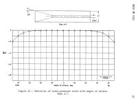
Its probably better to fall back on first principles and grab the flat plate Cd
from a bible like Hoerner's Fluid Dynamic Drag instead..... Also, the drag numbers are nonsensical at the higher Re of 4500000. The boundary layer code just cant cut it on the cylinder.
Hey Wait a minute! A tube is going to have a much larger aspect ratio in the real world. So a 1/4 inch by 7 inch tube will have an AR of 28, and a reduction in Re to 50000....
What does that look like?

Well, the Cd at 50000 is about 0.0727 (don't believe it) but its still trending the correct way..... higher at lower Re., and the the boundary layer is still messed up but you get the idea.
In relative terms though, you can see the effect of cross section on transition to turbulent (The dark line running along the span) and the relative increase in Cd between shapes.
In real world numbers, the drag of your mast might be for the symmetrical mast:
Drag in LBF = 0.5*Cd*Rho*V*V*S / G
Drag = 0.5 *0.0133 * .0752 LB/FT3 * 230 F/S* 230 F/S *0.0486 FT^2 / 32.2
Drag = 0.0399 lbf Symmetric foil.
From Hoerner's drag book, a cylinder at Re50000 has a Cd of about 1.2, so the drag of a 0.25 inch x 7 inch tube would be 0.9 LBF or 22 times the symmetrical shape.....
In summary, streamlined is better. Aspect ratio doesn't make a lot of difference.... probably because we are generating very little lift force.... I wish we could have been able to model the tube better...
And...that's not a lot of drag force...but it all adds up..
Hope this was as much fun to read as it was to prepare...
Chris