Van's Air Force

The definitive Van's Aircraft support community! Buying, building or flying an RV? Join our exclusive family of mentors and enthusiasts!

BNC bulkhead connector

Clayvt

Well Known Member
Patron
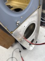
I’m putting in a bulkhead connector for my archer nav antenna and just had a quick question…
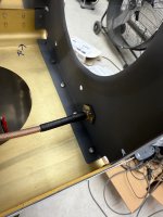
The connector creates continuity with the rib. I’m assuming this is not supposed to happen correct? I know next to nothing about comm wiring and how antennas actually work.
On the plus side, first time crimping a BNC connector I didn’t get a short between the body and center conductor so there’s that at least.
 

Attachments

  • IMG_7383.jpeg
    IMG_7383.jpeg
    1.6 MB · Views: 79
  • IMG_7384.jpeg
    IMG_7384.jpeg
    2 MB · Views: 79
At work, anything that touches a bulkhead or intercostal, gets electrically bonded to it. Doesn't matter if it's electrical, hydraulic or ECS, it's all bonded.
 
Thank you.
Would it hurt to put some fiber washers I ordered to try and isolate it? Or don’t even bother?
I wouldn’t bother. Since you asked, I ran coax from my nav out to an Archer in one piece, no connectors at all. Left a little extra at the tip to allow removal. IMHO half of electrical problems (10 years down the road) are due to connections.
 
I wouldn’t bother. Since you asked, I ran coax from my nav out to an Archer in one piece, no connectors at all. Left a little extra at the tip to allow removal. IMHO half of electrical problems (10 years down the road) are due to connections.
Agree.
I’ve had a few archers over the years. By far the best performance is with a straight run from the radio to the antenna. No connectors. BNC at the radio. Direct connection at the antenna. Bolt/rivet the antenna to the outboard rib.
 
It’s okay if the shield touches or is connected to the airframe (ground).
When I finished my RV in 2014, the wingtip Archer antenna did not seem to work when connected through a bulkhead fitting. An electrically isolated BNC bulkhead coupler solved the issue, and the antenna has worked great ever since. It does add one more connection, which as others mentioned isn't ideal, but performance has been flawless.


That said, since Clay's is already installed, perhaps leave it as-is and test when the plane's flying? Things are very accessible at the tip rib to change later if needed.
 
Last edited:
It’s okay if the shield touches or is connected to the airframe (ground).
It SHOULD be grounded. I think Bob was being polite.

A bulkhead fitting is maybe the best way to ground the shield and there is a reason for it to be.

There was a thread a while ago where an archer antenna did not work if the shield was grounded, and it was interpreted by some that leaving it all floating was best.
I can say with practical certainty that that antenna in question was bungled up and was operating in coat hanger mode.

Use a bulkhead fitting. Then the antenna will be like the rest of the antenna on the plane and be isolated from any noise on the shield which will be fed to the radio. With an ordinary antenna, the antenna is on one side of the skin and the coax is on the other. The bulkhead fitting will provide the same noise isolation to the archer. Signal sanitation.

ron
 
Last edited:
It SHOULD be grounded. I think Bob was being polite.

A bulkhead fitting is maybe the best way to ground the shield and there is a reason for it to be.

There was a thread a while ago where an archer antenna did not work if the shield was grounded, and it was interpreted by some that leaving it all floating was best.
I can say with practical certainty that that antenna in question was bungled up and was operating in coat hanger mode.

Use a bulkhead fitting. Then the antenna will be like the rest of the antenna on the plane and be isolated from any noise on the shield which will be fed to the radio. With an ordinary antenna, the antenna is on one side of the skin and the coax is on the other. The bulkhead fitting will provide the same noise isolation to the archer. Signal sanitation.

ron
The shield must be connected to the ‘short leg’ of the antenna, and that leg must be electrically and mechanically attached to the end rib. So the braid definitely does not ‘float’.
 
A connector mounted on the rib does nothing to antenna functionality (unless you screw up the BNC connectors).

But I assume you are hard mounting the antenna to the inside of the wing tip, thus the need to be able to disconnect the feed line if you want to remove the antenna. I suggest just hard mounting the antenna to the outboard wing rib and have the wingtip fit over it. No need for a connector.

I should add this is a homebrew antenna. The leg that goes out from the wing rib is longer than the Archer to take advantage of the total width of the wing tip (to enhance performance). The leg that runs fore to aft in the wingtip is nestled into the wingtip corner - it does not flop around.

Side note - this antenna cost me a couple of dollars in nylon fasteners. The rest came out of the scrap box.
Carl
 

Attachments

  • 20200403_135130.jpeg
    20200403_135130.jpeg
    1.6 MB · Views: 45
Last edited:
Normally isn't best to only ground the shield at one end? At work, I seem to recall that shields were normally to be grounded at the instrument end and left to 'float' at the sensor end.

But for an antenna, obviously the shield should be connected to the ground plane, and then also at the radio. It is not acting as just a shield, it is the ground reference for the antenna.
 
I mounted mine to the tip, properly attached via the screws, etc. I did that because I didn't like the idea of that big floppy antenna bouncing and jouncing up and down in the tip with every bump in the air. (And because that's how the instructions came). A bit of some soft of sealant or whatever I had around to keep it held down in the tip.
 
Normally isn't best to only ground the shield at one end? At work, I seem to recall that shields were normally to be grounded at the instrument end and left to 'float' at the sensor end.

But for an antenna, obviously the shield should be connected to the ground plane, and then also at the radio. It is not acting as just a shield, it is the ground reference for the antenna.
I’m not sure ‘ground reference’ is the right term, e.g., in a classic dipole antenna the shield must be connected to one half of the antenna, but that half is not grounded. Likewise, for our 1/4 wave vertical whips used for com, although we use the term ‘ground plane’ there is no requirement that the conducting plane actually be grounded. (Historically the name came about because early radio guys used the earth itself as a ‘ground plane’). For delivering power coax acts as a wave guide, with the ExB power traveling between the conductors. To keep the power from reflecting back, the load has to be matched to the coax impedance (50 ohms) and the currents flowing in the coax’s conductors have to keep flowing ‘forever’ (the currents in the coax’s conductors cannot tell the difference between an infinite line or a 50 ohms load). So yes, the shield definitely needs to be connected, both ends. But not necessarily to ground.
 
Isn't best to only ground the shield at one end? At work, I seem to recall that shields were only to be grounded at the instrument end (in this case, at the connection to the radio itself). The other end should float. Grounding both ends makes a ground loop -- not good, right?
That's the rule for audio , Steve. For RF the rule is more or less: "ground early and often" Ground loops are not a factor at radio freqs. Different realm, different analysis. Further, at VHF, a voltage difference on a wire can be expected in mere inches, whereas with audio, voltage propagation can be considered instantaneous.
A connector mounted on the rib does nothing to antenna functionality (unless you screw up the BNC connectors).

But I assume you are hard mounting the antenna to the inside of the wing tip, thus the need to be able to disconnect the feed line if you want to remove the antenna. I suggest just hard mounting the antenna to the outboard wing rib and have the wingtip fit over it. No need for a connector.

I should add this is a homebrew antenna. The leg that goes out from the wing rib is longer than the Archer to take advantage of the total width of the wing tip (to enhance performance). The leg that runs fore to aft in the wingtip is nestled into the wingtip corner - it does not flop around.

Side note - this antenna cost me a couple of dollars in nylon fasteners. The rest came out of the scrap box.
Carl
Good comments, Carl. I have done a hat full of simulations of the archer and similar antennas mounted on simulated wings. Getting more "height" as you have done is a good thing.
The way the coax shield is connected to the archer usually leaves a common inductive impedance allowing any noise on the coax shield to be shared with the antenna signal. The coax comes from a high noise area. At VHF freqs noise is easily coupled and propagated by a coax shield as a big wire inside a metal structure.
So, the point is "good practice". At VHF frequencies, grounding an object with a wire a few inch long is not grounding it at all. The wire has several ohms of impedance over which a voltage can exist. So, using a bulkhead fitting is a good way to keep things clean and sanitary.

ron
 
Last edited:
Wow, seems I have stirred up quite the "debate".
If I'm interpreting things correctly, the shield does get grounded, but I figured it did that on the antenna (one connection for the shield and the other for the center conductor) and then the mounting side of the antenna was the grounding point of the shield to the structure via rivets, screws what have you. Having a second grounding point at the fitting wont cause issues like a ground loop for VHF freqs?

I'm planning on riveting the antenna to the wingtip in conjunction with the hinge attach method. I did the bulk head connector to make it a little easier when/if the wingtip comes off.
 
I’m not sure ‘ground reference’ is the right term, e.g., in a classic dipole antenna the shield must be connected to one half of the antenna, but that half is not grounded.
Referencing a classic dipole antenna as an example can get confusing. A dipole really needs to be fed from a balanced transmission line. Remember that flat, two wire antenna cable that used to be used with what we now call "antenna TV"? That is a balanced transmission line. The same but opposite polarity currents run in each wire, hence the term "balanced". Coax is an unbalanced transmission line. The current in the center conductor is not the same as the current in the shield conductor.

So how does an unbalanced transmission line like coax work with an antenna, like a dipole, that requires a balanced feed? One of two ways. One, you can use a thing called a balun, short for balanced-unbalanced. This RF device converts one to the other. The other way is to rely on the fact that if you use a long enough length of lossy cable, at the antenna end the currents in the center conductor and shield tend to be more balanced. It isn't perfect but many times close enough for a dipole.

Most antennas we run into, however, are driven single ended (unbalanced) and so coax is the appropriate transmission line to use. Dipoles, yagis, and log-periodics (those goofy old TV antennas) are the few exceptions.
Or, you have antennas with an LC (inductive/capacitance) matching circuit like the Archer Wingtip antenna. The LC circuit, normally refereed to as a Gama Match, does the translation from unbalance to balance feed.

Carl
 
I wouldn’t bother. Since you asked, I ran coax from my nav out to an Archer in one piece, no connectors at all. Left a little extra at the tip to allow removal. IMHO half of electrical problems (10 years down the road) are due to connections.
I installed a bulkhead connector like is being done here. It was the only point of failure in my whole antenna system, and I have four anntennas. Once I was flying I could not receive a glideslope when flying an ILS with my Avidyne IFD540. The problem was in the bulkhead connector. I ended up removing it and running a single cable from the archer antenna in the wing tip all the way to the Avidyne GPS. Problem solved. As a result, I would recommend against installing that bulkhead fitting.
 
Back
Top