Using Van's standard 1/4" bent tube for pitot.
The Dynon OAT probe is fat: 5/16", round and 1" long.
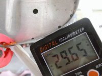
I want to add a simple rivet in the leading edge skin for AOA input. I assume the rivet hole should see the oncoming wind straight in at 30 degrees. Does the RV-4 wing really stall at around 30 degrees?
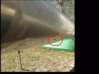
Does this location look about right? (about 18" forward of LE bottom skin edge, longerons level)

In order to minimize drag I'd like to put the AOA rivet, OAT probe and pitot in a line.
Should the OAT probe be located before or after the pitot tube? Would the oncoming air be heated by collision with the pitot tube?
Thinking about 3D printing a streamline for the OAT probe, in which case the OAT probe probably is best located after the pitot, if not significantly heated by encounter with pitot tube.
Finn
The Dynon OAT probe is fat: 5/16", round and 1" long.
I want to add a simple rivet in the leading edge skin for AOA input. I assume the rivet hole should see the oncoming wind straight in at 30 degrees. Does the RV-4 wing really stall at around 30 degrees?
Does this location look about right? (about 18" forward of LE bottom skin edge, longerons level)
In order to minimize drag I'd like to put the AOA rivet, OAT probe and pitot in a line.
Should the OAT probe be located before or after the pitot tube? Would the oncoming air be heated by collision with the pitot tube?
Thinking about 3D printing a streamline for the OAT probe, in which case the OAT probe probably is best located after the pitot, if not significantly heated by encounter with pitot tube.
Finn