

Van's Air Force

The definitive Van's Aircraft support community! Buying, building or flying an RV? Join our exclusive family of mentors and enthusiasts!

Adjusting Control Travel Limits on Flying RV-6

pmona

Member
I have about 10 hrs in my recently purchased RV-6 and have been documenting a number of things to produce a POH for the aircraft. I have really enjoyed flying the plane so far, but at some point, I would like to do some acro. That said while documenting the plane as it is built and setup today, I found the control travel for elevator and aileron outside of recommended travel limits and well below the recommended maximums and even minimums.

How much work is it to increase the travel limits on a finished aircraft?

Control throws as measured:

ControlUp/RightDown/Left
Elevator20.6°16.6°
Aileron L.27.3°14.0°
Aileron R.28.0°12.0°
Rudder35°35°
Flaps19.4° 1st36.4° 2nd

Van's documented travel limits:

Control

Max Up/Down

Min Up/Down

Elevator

30/25

25/20

Aileron L.

32/17

25/15

Rudder

35/35

30/30

Flaps

40-45
 
If you are planning to do aerobatics, I recommend that you increase the aileron and elevator travels to close to MAX limits.

Not a lot of work but you should get help from someone familiar with the process.

Looks like you're already good on rudder. I would not change the flap limit, as too much "down" flap can allow the leading edge to snap out from under the wing skin and "LOCK" them. I recommend no more than 38° for maximum flap deflection.
 
I’m not sure I understand your table relative to your control throws as shown, in terms of aileron movements. With the stick (control) down/left, the left aileron will be up (should be 25-32). I think what you are measuring is the up and down movement of each aileron (and elevators), and the left/right nomenclature’s really have no meaning, other than to make sure the controls are moving in the correct direction. In that case, some of your limits need to be adjusted. Control stops for your elevators are pretty easy - maybe just requires a file on the actual aluminum stop, although it could require an adjustment of the length of the big fat elevator push/pull tube back in the aft cabin. The aileron stops are thick aluminum angle pieces riveted to an aileron bracket - one on each aileron. That may require drilling out the rivets on the stop and moving it. There are some other options, but that is one way. Normally the aileron stop is riveted to the inboard aileron bracket that’s on the wing aft spar, and the steel aileron bracket on the aileron contacts the stop to limit throw - one on the left wing, one on the right. There are other ways to make a stop. On mine, I mounted the same type stop to the outboard aileron bracket. With my fiberglass wingtip removed, it is very easy to clamp the stop in just the right place on the bracket for drilling/riveting. I ran this through Vans Aircraft experts before doing it that way, and they were fine with it. At any rate, you do need to adjust your control stops to get the recommended control movements as designed. If you want your left and right ailerons to match each other up and down, you’ll need to access the aileron bell crank inside the wing(s) to adjust the length of the aileron push/pull tube(s).
 
Beware that moving the stick fore/aft causes small but measurable aileron movement. To properly check the aileron throw, clamp the elevator in a neutral position.
 
  • Like
Reactions: Mel
I’m not sure I understand your table relative to your control throws as shown, in terms of aileron movements. With the stick (control) down/left, the left aileron will be up (should be 25-32). I think what you are measuring is the up and down movement of each aileron (and elevators), and the left/right nomenclature’s really have no meaning, other than to make sure the controls are moving in the correct direction. In that case, some of your limits need to be adjusted. Control stops for your elevators are pretty easy - maybe just requires a file on the actual aluminum stop, although it could require an adjustment of the length of the big fat elevator push/pull tube back in the aft cabin. The aileron stops are thick aluminum angle pieces riveted to an aileron bracket - one on each aileron. That may require drilling out the rivets on the stop and moving it. There are some other options, but that is one way. Normally the aileron stop is riveted to the inboard aileron bracket that’s on the wing aft spar, and the steel aileron bracket on the aileron contacts the stop to limit throw - one on the left wing, one on the right. There are other ways to make a stop. On mine, I mounted the same type stop to the outboard aileron bracket. With my fiberglass wingtip removed, it is very easy to clamp the stop in just the right place on the bracket for drilling/riveting. I ran this through Vans Aircraft experts before doing it that way, and they were fine with it. At any rate, you do need to adjust your control stops to get the recommended control movements as designed. If you want your left and right ailerons to match each other up and down, you’ll need to access the aileron bell crank inside the wing(s) to adjust the length of the aileron push/pull tube(s).
Left/Right only applies to the rudder and has nothing to do with aileron directional control. Up/Down apply to the elevator and ailerons.
Thank you for the suggestions.
 
The required aileron down travel can probably be achieved by adjusting the pushrods and no need to change the hard stops for the ailerons. The hard stops set the up travel (which is OK) and the pushrods (two per aileron) set the down travel. There is an adjustment process to go through, setting the bell crank in the neutral position. Also need to ensure the re-adjusted pushrods do not end up contacting the rear wing spar where they pass through an odd shaped hole.

If adjusting the elevator hard stops it is very important to check that the bellcrank cannot go over-centre, same applies for any autopilot servos that may be fitted. (pitch and roll). For up elevator also check the base of the control column and confirm it is not hitting the wing spar bulkhead and that the rod end bearing is not binding where it is attached to the control column.
 
Speaking of going over center on bellcranks, be very careful of the aileron bellcranks. There is a very small tolerance on the early -6 models.
 
Speaking of going over center on bellcranks, be very careful of the aileron bellcranks. There is a very small tolerance on the early -6 models.
Not sure that you are meaning this Mel, but I've often found you need to be very careful to have sufficient threads engaged in the heim joints if you need to lengthen the rods.
 
Before you get too carried away with anything...I'd dis-connect your controls from the surfaces and see what and where the limiting factors are. There's lots of ways to do things wrong...and most are pretty easily corrected. I'd start there and report back.

S.
 
Rigging is pretty well documented in the build manual. If you don’t have it, I would suggest you get that and follow it. If you run into issues, then it’s time to circle back here.
If you’re not comfortable with that as a non-builder, get some help.
 
I've got things opened up for annual and am looking at what is limiting the elevator travel. Will inspect ailerons next.
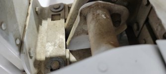
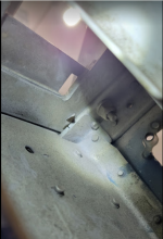
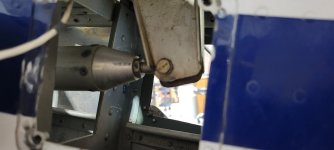
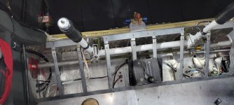
I don't know why this additional bar is bolted on here -- see picture from the top and bottom. From the bottom you can see the original aluminum angle which doesn't look like it was cut away or anything. Any ideas why this additional piece is bolted on other than to limit elevator travel?
top view.jpg

bottom.png
 
As you dig into this be sure you understand the mixer bell cranks on the ailerons and ow to center them. It is not just total throw here, but having the correct asymmetrical up/down. Well covered in the manual.
 
Rigging is pretty well documented in the build manual. If you don’t have it, I would suggest you get that and follow it. If you run into issues, then it’s time to circle back here.
If you’re not comfortable with that as a non-builder, get some help.
Please DOWNLOAD (free) the builder manual from VAN's and READ & COMPREHEND the rigging instructions completely. There are subtle things you MUST be aware of as well as understanding the interactions of stuff.
 
I've got things opened up for annual and am looking at what is limiting the elevator travel. Will inspect ailerons next.
I don't know why this additional bar is bolted on here -- see picture from the top and bottom. From the bottom you can see the original aluminum angle which doesn't look like it was cut away or anything. Any ideas why this additional piece is bolted on other than to limit elevator travel?
View attachment 123392

View attachment 123393
That part is clearly not part of the design... it is likely to compensate for something else that is not right.

Good advice given in the replies - step by step look at things, and most importantly, have someone who's been there give you a hand.
 
As Alex already mentioned, this bolted (cut-off washers?) flat piece is not "original". It was maybe added by someone feeling the need to reduce elevator travel... the builder would be a good source of knowledge, if not, I'd proceed as others have said.
 
I've got things opened up for annual and am looking at what is limiting the elevator travel.

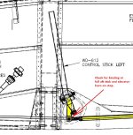
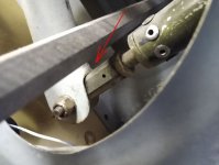
-7 shown below...pretty sure the issue also exists with the -6 and the other side-by-side models.

As travel is increased at the elevator stops, monitor clearance where the elevator pushrod meets the stick assembly, under the seat. At full aft travel it is possible for the shank of the rod end to contact the weldment where shown, which applies a bending load to the threads of the AN490. It mostly happens when the builder rigged the controls with the stick vertical while the elevator is centered. It needs to lean forward with the elevator centered, as shown on the plans.

Stick.jpgWrong.jpg

I don't know why this additional bar is bolted on here -- see picture from the top and bottom. From the bottom you can see the original aluminum angle which doesn't look like it was cut away or anything. Any ideas why this additional piece is bolted on other than to limit elevator travel?

I seem to recall a case where the horizontal stabilizer was attached somewhat forward of its intended position.

Paul, is there a down elevator stop installed? Can't quite tell from the photos.
 
-7 shown below...pretty sure the issue also exists with the -6 and the other side-by-side models.

As travel is increased at the elevator stops, monitor clearance where the elevator pushrod meets the stick assembly, under the seat. At full aft travel it is possible for the shank of the rod end to contact the weldment where shown, which applies a bending load to the threads of the AN490. It mostly happens when the builder rigged the controls with the stick vertical while the elevator is centered. It needs to lean forward with the elevator centered, as shown on the plans.

View attachment 123425View attachment 123426


I seem to recall a case where the horizontal stabilizer was attached somewhat forward of its intended position.

Paul, is there a down elevator stop installed? Can't quite tell from the photos.
I do not see a down stop for the elevator. I'll have to pull the floor panels again and look for the bind point you have shown.
The other thing worth mentioning is, there trim lever trims the entire elevator, no trim tab.

I was also looking at the ailerons today and could not see a stop for either aileron. I put a pin in the aileron bellcrank alignment hole and checked the zero on the right wing - looks to be .8° high when compared to the wing tip. Stops up and down feel almost spongy like it is limited by stick travel.
I have enjoyed flying this plane for the past year with no complaint. I am only looking into the travel limits because I would like to do some acro and am primarily concerned with the elevator travel in the up direction.

20260714_120255.jpg20260714_135931.jpg
 
Back
Top