CharlieWaffles
Well Known Member
Considering these are used for several different models - should this thread be moved to the General forum for greater awareness across the different models? Thinking from a safety and possible awareness effort.


(c) In either case, install the second reed valve as an automatic positive pressure relief. (install photo in post 98)
Continue with an evacuator or not? All users will need to make their own decision. If you elect to keep the exhaust tap, I'd suggest this approach:
(a) 25 hr inspection intervals if operated as delivered from Anti-Splat.
(b) 25 hr inspection intervals if operating an experimental system or component of your own design.
(c) In either case, install the second reed valve as an automatic positive pressure relief. (install photo in post 98)
I like the benefits of negative case pressure, so I will continue to experiment, following (b) and (c). The goal is a non-coking tap.
Special request: please report ANY problem with a relief valve installation immediately. So far, it worked just as intended for Vic (provided a positive pressure relief after exhaust tap blockage), but that's just one case. If there is an unknown issue with the relief valve installation, everyone should be made aware ASAP.

I would like to install the second reed valve but do not have the means to fabricate a T connector. I have been unsuccessful in locating a metal connector. Has anyone found a good source?
Considering these are used for several different models - should this thread be moved to the General forum for greater awareness across the different models? Thinking from a safety and possible awareness effort.
I would like to install the second reed valve but do not have the means to fabricate a T connector. I have been unsuccessful in locating a metal connector. Has anyone found a good source?
...I like the benefits of negative case pressure, so I will continue to experiment, following (b) and (c). The goal is a non-coking tap...
would like to install the second reed valve but do not have the means to fabricate a T connector. I have been unsuccessful in locating a metal connector. Has anyone found a good source?
I'm trying to visualize this:
So we install the Antisplat per instructions, with the main breather line going to the NAPA-type valve first then terminating in the saddle penetrating the exhaust.
The "safety" line coming off the T, on the other hand, is simply an open tube like that of the Van's stock setup and it can be routed wherever we want, perhaps over the other exhaust pipe. Is this basically correct?
What's to keep the oil from going out the open safety tube rather than to the valve and exhaust saddle? The suction created by the exhaust does this?
Does the above suggest I'm understanding this correctly?
Newer diesel powered light trucks have exhaust tip augmentors that draw in fresh air to dilute the particulates. Any reason the same concept could not be applied to an aircraft engine? Exhaust flow combined with cowl exit airflow should be able to generate negative pressure in this venturi. Benefits include no need for the reed check valve, and the temperature of the stub pipe will be well below the coking temperature.
Might not have quite the "sucking power" of the reed valve tapped into the primary tube, but should still pull some, and keep the belly clean.


I have decided to remove the valve and stem. I am going to keep the separator and will run the line to drip on the exhaust like the stock setup, so I will still benefit from having the separator and clean belly.
I ran this way for a while until the saddle version became available. I say it cut down on the oily belly maybe 50% at best. I still had an oily belly, oily engine mount, oily firewall, etc.
I ran this way for a while until the saddle version became available. I say it cut down on the oily belly maybe 50% at best. I still had an oily belly, oily engine mount, oily firewall, etc.
Ernest, I don't know how much clearer some of us can be. This is a dangerous configuration, and someone is going to have a serious problem. Over a year ago I was told I was the ONLY one having this problem. There is now overwhelming evidence that it is the configuration. And as I stated before, others tried this 30 years ago and had the same problems.
Vic


This is obviously conductive heat from the pipe and perhaps some heating from the exhaust impingement on the small piece that is in the exhaust flow.
When I added the relief valve after just about 1.0 hours from completely cleaning the coke off the inside of the pipe, there was a very small buildup starting.
Most of us are flying with all electric panels, there is a vacuum pump pad blocked off on the engine that could be put to use.............
I had a wet vac pump pulling on the breather on my RV-6. I put a flapper-door check valve with one side vented to ambient on the intake side of the pump so that in the event of the pump failure the breather functioned normally. The limiting factor to the system was the fuel pump. Since it is vented to the crankcase, the pump would quit if a high vacuum was pulled. It worked well but I had to dial back the vacuum, using a simple orifice at the inlet of the pump.
...The photos below are of our double walled saddle mount that is currently being tested. This should eliminate this heat transfer completely. The inner tube that carries the blow-by products is welded only at the cooler top fitting and has .025" clearance all around. This insulates it from the hotter outer tube that is perpetuating the buildup or coking.
.
It also seems that any major hard buildup is on systems that the exhaust valve mounting tube was welded into the exhaust pipes and not on the saddle mounts. We are and have been working and testing many different designed parts to eliminate the possibility of this happening and have several in use now, building time. We will report the results when they have accumulated viable, credible information at 20, 40, 60, etc hours and when available. Thanks, Allan

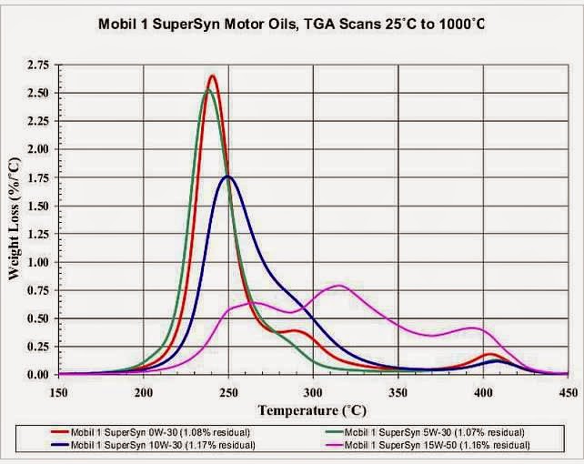
....say 200C to 300C on Bill's chart. It would be nice to find a similar chart for our motor oils. What search terms might find it?
Here is a little background on motor oil testing.
If we have any RVers that work at SwRI in San Antonio, they would have access to some proprietary data (and certainly public) that we would have to pay for. They certainly have data on many oils as they do the qualification testing on single cylinder engines for piston deposits etc. They NEVER would publish, or post, definitive brand data, but might give us a delta for petroleum vs full synthetic temps.

