Just wondering how many RV-14's flying have had additional rudder trim added after the build.

Van's Air Force
You are using an out of date browser. It may not display this or other websites correctly.
You should upgrade or use an alternative browser.
You should upgrade or use an alternative browser.
rudder trim
- Thread starter USN bullet
- Start date


czechsix
Well Known Member
Poll: What rudder trim does your RV-14(A) need in cruise?
Now that there are enough RV-14s and -14As flying to get a meaningful statistical trend, I'm curious what rudder trim each model typically needs in cruise to center the ball. Generally I've seen more -14s with tabs for left rudder trim, and more -14As with tabs for right rudder trim, but I've...
vansairforce.net
In cruise my yaw damper (14A) offsets the 1/4 ball needed, climb just lean slightly on my right pedal till I get to cruise. Seems some trim tabs are adding a lot of drag when the majority of the time very little needed. 10 about the same.Just wondering how many RV-14's flying have had additional rudder trim added after the build.
@dmattmul , I'm not off a 1/4 ball, but what yaw damper settings did you end up with?In cruise my yaw damper (14A) offsets the 1/4 ball needed, climb just lean slightly on my right pedal till I get to cruise. Seems some trim tabs are adding a lot of drag when the majority of the time very little needed. 10 about the same.
Max Torque = 100%@dmattmul , I'm not off a 1/4 ball, but what yaw damper settings did you end up with?
Servo Gain = 1.50
@dmattmul agree with Walt here -- the GSA28 is going to be "driving" constantly, would be better to shim the rudder trailing edge -or- adjust the gear leg fairings -or- go nuts and build in a servo controlled rudder trim on the trailing edge - tie that to the yaw-GSA 28 and let the G3X resolve the displacement via the trim tab motor, not the rudder servo...Trim tab should be used to center ball at cruise. YD is not meant to correct trim routinely.
Last edited:
Let me gather data before permanently adding drag to my airframe. How much offset I needed in cruise was depended on cruise speed but need to review.@dmattmul agree with Walt here -- the GSA28 is going to be "driving" constantly, would be better to shim the rudder trailing edge -or- adjust the gear leg fairings -or- go nuts and build in a servo controlled rudder trim on the trailing edge - tie that to the yaw-GSA 28 and let the G3X resolve the displacement...
YD torque (%) in cruise varied from ~+6% to ~-8% depending in cruise while pitch torque (%) with auto-trim varied from ~+7% to ~-10% at lower cruise speeds to slightly increased % torque values at higher cruise speeds. Roll torque (%) was statistically greater as I do not have auto-trim on that axis. What would be considered an excessive amount of torque%? For now, I'll continue to monitor the data.
My comment about YD could offset the ball 1/4 of a ball was meant that it has capability to do so, it's actually greater but I'll continue to review.
")
Found this flight from a few months ago which was rememberable for its turbulence and wish I had a 5-point harness in the 10 like I had in my 14. I think looking at % torque on these servos is a reasonable way to determine if a more permanent way to correct would be needed?

Last edited:
good idea bjd. I didn't keep a count but I saw quite a few at Airventure 2023 with external mods to the rudder. I also would like more info before I tack on trim device to my rudder.
I guess it was dmatt. that wanted to gather more data. Yep me too.
It’s all “drag” of some stipe - displacing the rudder by pulling/pushing on the cables, or by displacing the rudder by trailing edge devices (wedges, shims, tabs).Let me gather data before permanently adding drag to my airframe. How much offset I needed in cruise was depended on cruise speed but need to review.
YD torque (%) in cruise varied from ~+6% to ~-8% depending in cruise while pitch torque (%) with auto-trim varied from ~+7% to ~-10% at lower cruise speeds to slightly increased % torque values at higher cruise speeds. Roll torque (%) was statically greater as I do not have auto-trim on that axis. What would be considered an excessive amount of torque%? For now, I'll continue to monitor the data.
My comment about YD could offset the ball 1/4 of a ball was meant that it has capability to do so, it's actually greater but I'll continue to review.
Assuming that yaw in cruise regime is the most force/energy expended over a given time, I submit that cleaning up the alignment of gear leg fairings is the biggest bang for the buck…
in my case, gear fairings did not change my ball out to the right at 140 KTA (1/2 ball out) but accelerate to 170 KTA made centering the ball (ball fully out to the right) a great effort, and locking my leg straight was only a short-term solution.
A full ball at cruise is a lot.
Is it a 14 or a 14A?
There’s no TE radiuses to mess up and no incidence or alignment issues unless there’s some gross wing twist introduced during building. Every one I’ve seen the rear spar clecos into the spar carry thru first time. (Which is amazing as a side note)
So if you’re content the control surface rigging is good then that only leaves the gear leg fairings or the wheel pants.
If it’s an A then it could also be breakout force/nose wheel prop slip stream interaction (but that’s unlikely a full ball at cruise speed - it’s usually transient and you can tell by yawing the plane)
I would closely look gear leg fairing alignments before making any kind of adjustments to the airframe.
Maybe take all the gear leg and wheel fairings off and go fly as a first step. If you still have a 1/2 or 3/4 ball out then you can rule out the fairings, but then we back to first base which is rigging and airframe alignment")
Is it a 14 or a 14A?
There’s no TE radiuses to mess up and no incidence or alignment issues unless there’s some gross wing twist introduced during building. Every one I’ve seen the rear spar clecos into the spar carry thru first time. (Which is amazing as a side note)
So if you’re content the control surface rigging is good then that only leaves the gear leg fairings or the wheel pants.
If it’s an A then it could also be breakout force/nose wheel prop slip stream interaction (but that’s unlikely a full ball at cruise speed - it’s usually transient and you can tell by yawing the plane)
I would closely look gear leg fairing alignments before making any kind of adjustments to the airframe.
Maybe take all the gear leg and wheel fairings off and go fly as a first step. If you still have a 1/2 or 3/4 ball out then you can rule out the fairings, but then we back to first base which is rigging and airframe alignment
Richard, it's a 14A. at 140 to 150 KTAS there was no change when we added the wheel pants ball about 1/2 outA full ball at cruise is a lot.
Is it a 14 or a 14A?
There’s no TE radiuses to mess up and no incidence or alignment issues unless there’s some gross wing twist introduced during building. Every one I’ve seen the rear spar clecos into the spar carry thru first time. (Which is amazing as a side note)
So if you’re content the control surface rigging is good then that only leaves the gear leg fairings or the wheel pants.
If it’s an A then it could also be breakout force/nose wheel prop slip stream interaction (but that’s unlikely a full ball at cruise speed - it’s usually transient and you can tell by yawing the plane)
I would closely look gear leg fairing alignments before making any kind of adjustments to the airframe.
Maybe take all the gear leg and wheel fairings off and go fly as a first step. If you still have a 1/2 or 3/4 ball out then you can rule out the fairings, but then we back to first base which is rigging and airframe alignment
That’s a big change. I think something must be moving, and the only thing that comes to mind is the nose wheel. If possible repeat the experiment, have an observer with binoculars look at the nose wheel.in my case, gear fairings did not change my ball out to the right at 140 KTA (1/2 ball out) but accelerate to 170 KTA made centering the ball (ball fully out to the right) a great effort, and locking my leg straight was only a short-term solution.
Also look at how straight the trailing edge of the rudder is. I was involved with a 14 that took a huge amount of rudder force to keep the ball centred. Everything was looked at including borrowing my rudder to see if it made a difference. It did. We ended up building a new rudder. The trailing edge of the original rudder was displaced slightly off of centre.
We began inspecting N12YY for out of center ball. Vert Stab washer in place correctly. Nose wheel breakout was 7 lbs. Re torqued nose wheel to 26 pounds break out. We will fly this coming week, and I will report back after the flight. Cheers
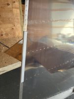
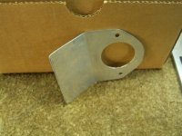
That trim tab is great. I like how it takes advantage of the existing holes for the tail light. Is it aluminum, and how thick material did you use? I'm thinking about 3D printing a few candidate designs to get the shape and size/drag right.Here's my RV14A rudder trim tab that mitigates the half ball width of uncoordination otherwise. View attachment 114789
bwagner
Active Member
I used some leftover 0.032" 2024-T3 for that trim tab. The design came from a related VAF thread. It took just a single down-sizing iteration. I only resorted to adding this after an exhaustive alignment check of an otherwise completely stock kit build. My prior RV-7A build required almost exactly this same amount of correction. If the addition is measurably scrubbing top end speed; it's still worth it to me to not be constantly having to keep the nominal right pedal pressure applied such is my constant coordinated flight OCD...
Hard to tell with the photo, but it appears that the tab slightly obscures the tail nav/ strobe on the port side. Is there any location - aft, port side - where you cannot see either the port side nav or the aft nav light? Same question for the strobes.Here's my RV14A rudder trim tab that mitigates the half ball width of uncoordination otherwise. View attachment 114789
Yeah - it's too tall. Should be like this:Hard to tell with the photo, but it appears that the tab slightly obscures the tail nav/ strobe on the port side. Is there any location - aft, port side - where you cannot see either the port side nav or the aft nav light? Same question for the strobes.

Just keep in mind any permanent wedge or other permanent mods might add drag to one side when you really don't need drag, (IE reduced TAS) at that pitch attitude.That trim tab is great. I like how it takes advantage of the existing holes for the tail light. Is it aluminum, and how thick material did you use? I'm thinking about 3D printing a few candidate designs to get the shape and size/drag right.
jcbarker
Well Known Member
I had two out of trim issues:
In cruise 24X24 5K'
1. right wing heavy
2. rudder 1/2 ball to the left (needed considerable pressure on the left rudder pedal. Very annoying on a flight of over 15')
Couple of data points:
- factory wings, ailerons and flaps.
- checked rigging and alignments. All good.
First I attacked the out of trim rudder condition:
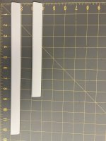
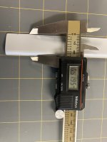
Fabricated some wedges out of straight grain cedar. It's light and stiff (see pictures). I started with about a 9" length. I attached with packing tape. (Guess what? It's also 200mph tape). Test flew. Not enough. Added 3" inches. Test flew. Almost perfect so I made a new one 13" long.
Next wing heavy condition:
Why does it have a right wing heavy. Well, as someone posted on this site, there's a heavy AP servo sitting about 10' out in the wing. Huh! Soooo...
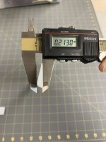
Made another wedge about 6" long and attached it the the underside of the left aileron. Test flew. Not enough. Added another 21/2". Test flew. Nearly perfect. Needed to trim 1/2" off the rudder wedge.
Now to give them a coat of heavy build sandable primer and two coats epoxy primer. This time I permanently attached them using, wait for it..., JB Weld! Of course I sanded and cleaned the area where they will be attached.
It is so much more enjoyable to fly an in-trim airplane!


In cruise 24X24 5K'
1. right wing heavy
2. rudder 1/2 ball to the left (needed considerable pressure on the left rudder pedal. Very annoying on a flight of over 15')
Couple of data points:
- factory wings, ailerons and flaps.
- checked rigging and alignments. All good.
First I attacked the out of trim rudder condition:
Fabricated some wedges out of straight grain cedar. It's light and stiff (see pictures). I started with about a 9" length. I attached with packing tape. (Guess what? It's also 200mph tape). Test flew. Not enough. Added 3" inches. Test flew. Almost perfect so I made a new one 13" long.
Next wing heavy condition:
Why does it have a right wing heavy. Well, as someone posted on this site, there's a heavy AP servo sitting about 10' out in the wing. Huh! Soooo...
Made another wedge about 6" long and attached it the the underside of the left aileron. Test flew. Not enough. Added another 21/2". Test flew. Nearly perfect. Needed to trim 1/2" off the rudder wedge.
Now to give them a coat of heavy build sandable primer and two coats epoxy primer. This time I permanently attached them using, wait for it..., JB Weld! Of course I sanded and cleaned the area where they will be attached.
It is so much more enjoyable to fly an in-trim airplane!
Attachments
I think it was ~30° -- no math, just a whole bunch of TLAR, then a test flight...For the RV'ers that are using this rudder trim tab... Just how much of an angle are you putting on the bend?
