
Van's Air Force
You are using an out of date browser. It may not display this or other websites correctly.
You should upgrade or use an alternative browser.
You should upgrade or use an alternative browser.
RV-15 #150046 (Wing Kit)
- Thread starter MCA
- Start date


Flaps.


Test fit the frame inside to skin to verify everything lined up before riveting.
Don't forget to dimple these holes on each rib:


I used a 3x rivet gun and offset rivet set for the rivets. This is my preferred rivet set for the wing kit:


Recommend building both at same time to verify mirror images.

The trailing edge needed a good bend, using the jig described in section 5. Recommend 2x6x10 (flaps are long) boards with hinge. The flaps trailing edge doesn't bend easily. Take your time and work towards a proper bend.
30 grams of sealer, 33 total. Just about right for each flap.

No pics here, but I used about 6 pieces of duct tape to bring the VGs around over the top skin and hold them roughly in place. That'll get the bend to the point you can put in clecos to get it all aligned properly.

Test fit the frame inside to skin to verify everything lined up before riveting.
Don't forget to dimple these holes on each rib:
I used a 3x rivet gun and offset rivet set for the rivets. This is my preferred rivet set for the wing kit:
Recommend building both at same time to verify mirror images.
The trailing edge needed a good bend, using the jig described in section 5. Recommend 2x6x10 (flaps are long) boards with hinge. The flaps trailing edge doesn't bend easily. Take your time and work towards a proper bend.
30 grams of sealer, 33 total. Just about right for each flap.
No pics here, but I used about 6 pieces of duct tape to bring the VGs around over the top skin and hold them roughly in place. That'll get the bend to the point you can put in clecos to get it all aligned properly.
Last edited:


Finished the right (second) flap. Riveting the flat surfaces goes quite fast. The front top section takes some time, though. Lots of clecos and I only went one rivet at a time due to the springiness in sheet metal.

I also decided to put a slight roll in the back edges of the outside section of the lower skin that wraps up around to the front. Is this a big deal? Probably not, but it does make me feel better about it. Here is the front edge of the left flap (not rolled). You can see the sheet metal pulls up a tad.

Here the front edge of the right flap (rolled). You can see the sheet metal lays flat.

And a top view - you can see the slight crease from the roll.

And a zoom in:

I only rolled the ends, not the individual VGs.
I also decided to put a slight roll in the back edges of the outside section of the lower skin that wraps up around to the front. Is this a big deal? Probably not, but it does make me feel better about it. Here is the front edge of the left flap (not rolled). You can see the sheet metal pulls up a tad.
Here the front edge of the right flap (rolled). You can see the sheet metal lays flat.
And a top view - you can see the slight crease from the roll.
And a zoom in:
I only rolled the ends, not the individual VGs.
Attachments
Last edited:

Completed the aileron control rods and aileron mounting brackets.
The KAIs imply extra slop between the insert and the tube, but mine were a solid press fit. A bench vice worked well as a press.


Made the L and R side aileron attach brackets. (left shown below)

For the bracket below on the left, the five AN470 rivets are incorrectly spec'd at -11 in the KAIs but should be -9.

The KAIs imply extra slop between the insert and the tube, but mine were a solid press fit. A bench vice worked well as a press.
Made the L and R side aileron attach brackets. (left shown below)
For the bracket below on the left, the five AN470 rivets are incorrectly spec'd at -11 in the KAIs but should be -9.
Decided to get started on the wings in earnest while waiting for the aileron tube and weights. It's worth mentioning that I've received incorrect rivets form both Vans and ACS. So now I always measure any new bag of rivets as well as ensure it is the correct type (426 or 470).
First the aileron brackets were made for both the left and right sides. Interestingly, the KAIs don't have a way to sign off on building the right side parts, so I just make a separate column on each page for the right side parts.
It was time to start assembling the ribs and installing the aileron brackets. When riveting parts to the rear main spar, I found it easiest to buck the solid rivets rather than squeeze them. Did I mention that tungsten bucking bar is fire. All the rivets for the aileron brackets were squeezed.


Using the left side to double-check the right side assembly.

And the aft ribs needed priming.

The EAA SportAir workshop for fiberglass was super helpful for me, as that is an area I'm not very skilled. I made a test batch of 105/206 West Systems epoxy with 50/50 micro mixed in to test how filling in the rivets would work. Since this will go in the water (hopefully on floats some day), I want to ensure that water does not get captured in the rivet recesses and contribute to further corrosion.

After trying several approaches, I found that using a toothpick with a dab of epoxy/micro mix worked well to apply just a little bit into the hole. I'll sand it tomorrow and see how it works.

First the aileron brackets were made for both the left and right sides. Interestingly, the KAIs don't have a way to sign off on building the right side parts, so I just make a separate column on each page for the right side parts.
It was time to start assembling the ribs and installing the aileron brackets. When riveting parts to the rear main spar, I found it easiest to buck the solid rivets rather than squeeze them. Did I mention that tungsten bucking bar is fire.
All the rivets for the aileron brackets were squeezed.Using the left side to double-check the right side assembly.
And the aft ribs needed priming.
The EAA SportAir workshop for fiberglass was super helpful for me, as that is an area I'm not very skilled. I made a test batch of 105/206 West Systems epoxy with 50/50 micro mixed in to test how filling in the rivets would work. Since this will go in the water (hopefully on floats some day), I want to ensure that water does not get captured in the rivet recesses and contribute to further corrosion.
After trying several approaches, I found that using a toothpick with a dab of epoxy/micro mix worked well to apply just a little bit into the hole. I'll sand it tomorrow and see how it works.
Last edited:
So the epoxy with micro works well. Even though I used the 206 slow epoxy (next step: buy the 209 extra slow hardener) it only gave us about 10 minutes before it started to harden, with spring here and the temps warming up. But a dab of epoxy with a toothpick held vertically works well, and it sands down nicely with 220 then 400 grit. Also needed is a scale that goes to .01 grams to measure the epoxy in small batches.
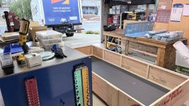
The shop is really filling up. Once the aileron weights and counterbalance tubes show up I can get the ailerons finished. And I expect to have the rivets filled on the flaps and ailerons next weekend. Hopefully those parts can then go out to the hangar.

The shop is really filling up. Once the aileron weights and counterbalance tubes show up I can get the ailerons finished. And I expect to have the rivets filled on the flaps and ailerons next weekend. Hopefully those parts can then go out to the hangar.

So the epoxy with micro works well. Even though I used the 206 slow epoxy (next step: buy the 209 extra slow hardener) it only gave us about 10 minutes before it started to harden, with spring here and the temps warming up.
There's a trick for that.
Epoxy/micro exotherms in the cup faster than epoxy alone, because the microballoons are insulators...the cure heat can't escape the lumped mass. I treat 4 mil plastic sheet as a shop essential, like paper towels. Mix the micro, then dump the whole cup out on a piece of plastic sheet and spread it so it's maybe 1/4" thick. Now it will have about the same working time as plain epoxy.
Thanks Dan, will try that.There's a trick for that.
Epoxy/micro exotherms in the cup faster than epoxy alone, because the microballoons are insulators...the cure heat can't escape the lumped mass. I treat 4 mil plastic sheet as a shop essential, like paper towels. Mix the micro, then dump the whole cup out on a piece of plastic sheet and spread it so it's maybe 1/4" thick. Now it will have about the same working time as plain epoxy.
Some progress this weekend.
The fuel tanks were sealed, now waiting a few days for the proseal to dry before pressure testing. On the CEIS fuel level senders, I elected to use their gasket rather than proseal. We installed these on a Cessna a few years back and the gasket has been working fine. It's important to remove the anodization for the electrical connection.


Thisis how the CiES senders are wired to G3X:

Note the locking gas cap (available from ACS).

Installed the aileron weights on the backing plate. (still waiting for the aileron counterbalance tube, and noticing that people with higher kit numbers do have them. Oh well.)

Prepped the wing skins. Nothing of note here other than some of the skins had the wrong part number on them. It's pretty easy to figure out the correct if you trust the drawings.


The fuel tanks were sealed, now waiting a few days for the proseal to dry before pressure testing. On the CEIS fuel level senders, I elected to use their gasket rather than proseal. We installed these on a Cessna a few years back and the gasket has been working fine. It's important to remove the anodization for the electrical connection.
Thisis how the CiES senders are wired to G3X:
Note the locking gas cap (available from ACS).
Installed the aileron weights on the backing plate. (still waiting for the aileron counterbalance tube, and noticing that people with higher kit numbers do have them. Oh well.)
Prepped the wing skins. Nothing of note here other than some of the skins had the wrong part number on them. It's pretty easy to figure out the correct if you trust the drawings.
Last edited:
Marc,Decided to get started on the wings in earnest while waiting for the aileron tube and weights. It's worth mentioning that I've received incorrect rivets form both Vans and ACS. So now I always measure any new bag of rivets as well as ensure it is the correct type (426 or 470).
First the aileron brackets were made for both the left and right sides. Interestingly, the KAIs don't have a way to sign off on building the right side parts, so I just make a separate column on each page for the right side parts.
It was time to start assembling the ribs and installing the aileron brackets. When riveting parts to the rear main spar, I found it easiest to buck the solid rivets rather than squeeze them. Did I mention that tungsten bucking bar is fire.
View attachment 113562
View attachment 113563
View attachment 113564
View attachment 113565
Using the left side to double-check the right side assembly.
View attachment 113566
And the aft ribs needed priming.
View attachment 113567
The EAA SportAir workshop for fiberglass was super helpful for me, as that is an area I'm not very skilled. I made a test batch of 105/206 West Systems epoxy with 50/50 micro mixed in to test how filling in the rivets would work. Since this will go in the water (hopefully on floats some day), I want to ensure that water does not get captured in the rivet recesses and contribute to further corrosion.
View attachment 113568
After trying several approaches, I found that using a toothpick with a dab of epoxy/micro mix worked well to apply just a little bit into the hole. I'll sand it tomorrow and see how it works.
View attachment 113569
Thanks for all the great pictures. A friend has built 2 Slings and he used Super Fill to fill the rivets. Not sure if it works any better than Epoxy and micro balloons. It is very easy to sand.
I'll giver Super Fill a try. Looks perfect.
Main wing spars will arrive on Friday, and due to the limited room in my shop I am planning to prep all the skins and misc parts prior to actually assembling the wing spars to the tank.
With the skins primed, next step is to rivet the nut plates to the access panels. Clearly someone at Van's really like access panels, as there are lots of 'em. It might almost be easier to do this job once the skins are installed, but I am doing them now as per plans. The recessed backing plate for each access hole is really nice, but precludes any ability to back rivet the nut plates on.

I bought a foot switch and taped the squeezer valve open, and mounted the pneumatic squeezer in the bench vice. It works really well, as both hands can be freed up to hold the workpiece in the right location.

Next prep item was the landing light mounts.


The inside was painted black and FlyLEDs test fit. I'm really excited to see these working in the distant future.

Main wing spars will arrive on Friday, and due to the limited room in my shop I am planning to prep all the skins and misc parts prior to actually assembling the wing spars to the tank.
With the skins primed, next step is to rivet the nut plates to the access panels. Clearly someone at Van's really like access panels, as there are lots of 'em. It might almost be easier to do this job once the skins are installed, but I am doing them now as per plans. The recessed backing plate for each access hole is really nice, but precludes any ability to back rivet the nut plates on.
I bought a foot switch and taped the squeezer valve open, and mounted the pneumatic squeezer in the bench vice. It works really well, as both hands can be freed up to hold the workpiece in the right location.
Next prep item was the landing light mounts.
The inside was painted black and FlyLEDs test fit. I'm really excited to see these working in the distant future.
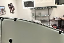
This is the Garmin pitot tube mast. Turns out it does not fit into the brackets provided with the kit. You'll see in the image below that the holes don't line up.

The mast does come with its own mounting bracket, which does fit. Since Van's isn't sharing what they're doing in the future for a pitot mast, I'll just install the Garmin mount. The other option is to install what came with the kit, and assume that Van's will provide an appropriate (and likely less expensive) pitot mast in the future. That's probably easiest, but of course not that path I'm taking.

The mast does come with its own mounting bracket, which does fit. Since Van's isn't sharing what they're doing in the future for a pitot mast, I'll just install the Garmin mount. The other option is to install what came with the kit, and assume that Van's will provide an appropriate (and likely less expensive) pitot mast in the future. That's probably easiest, but of course not that path I'm taking.
MarcI'll giver Super Fill a try. Looks perfect.
Main wing spars will arrive on Friday, and due to the limited room in my shop I am planning to prep all the skins and misc parts prior to actually assembling the wing spars to the tank.
With the skins primed, next step is to rivet the nut plates to the access panels. Clearly someone at Van's really like access panels, as there are lots of 'em. It might almost be easier to do this job once the skins are installed, but I am doing them now as per plans. The recessed backing plate for each access hole is really nice, but precludes any ability to back rivet the nut plates on.
View attachment 114482
I bought a foot switch and taped the squeezer valve open, and mounted the pneumatic squeezer in the bench vice. It works really well, as both hands can be freed up to hold the workpiece in the right location.
View attachment 114483
Next prep item was the landing light mounts.
View attachment 114484
View attachment 114485
The inside was painted black and FlyLEDs test fit. I'm really excited to see these working in the distant future.
View attachment 114486
Which FlyLEDs did you install.
Flyboys Accessories is a stocking distributor for FlyLEDs with service second to none!The -15 was designed to use these lights from FlyLEDs.
Tail Dragger Seven - for Van's RV-15
You can find them here. Currently they are shipped from Australia but they may be sold by Van's soon.


I saw that elsewhere as well. Dissimilar metals is all I can think of, but we painted the weights and primed the brackets instead.Is there a reason to prime the aileron counterbalance tubes, which are stainless?
Hat tip for the black paint now suggestion!
The aileron counterbalance tubes came in so it was time to install them. Many thanks to the previous posters that figured lots of this out.
First step was to figure out which way the tube goes on correctly (great guidance in the RV-15 Wiki). I found it helpful to tape on the tube and then cleco the LE skin on to double check that everything lines up properly - and to know which holes to countersink. It should be dead nuts on if everything is right.
Then on to countersink the holes in the tube. It was hard to judge exactly how deep these should go, and the countersink tended to wander quite a bit because there's nothing to support it from behind. These worked OK, but I made them slightly larger for the other aileron.

My neighbor had some issue with the internal ribs creating dents through the skin, so I figured I'd sand down that part a bit. Turns out it really wasn't necessary as everything came together quite well. (Maybe he was forcing things?)

I used a single 960 washer under the screw head and the nuts went on just fine and didn't bottom out.

Additionally, some Dowsil 737 silicone (Proseal would work too) was used on the middle rib to minimize the rib vibrating on the tube. I'm not sure why this metal to metal unsecured contact is OK.

The bottom side of the LE skin laid up nicely because of the dual flat surfaces, but the top was curved so I decided to put a shallow roll along the long aft edge. It was OK without the roll, but IMO better with the roll (which takes about 2 minutes to do). Here's a picture with the rivets in.

Learning a bit from my neighbor's trials and tribulations, it worked well to cleco the LE skin as follows:
1. Cleco all along bottom long edge of the LE skin
2. Cleco up the three ribs going forward. (starting in center, then edges)
3. Push the skin around the tube and cleco the forward hole on the top front of the LE skin
4. Work your way backward and then cleco the long top aft edge.
5. Rivet per instructions.
At least for me, everything lined up nicely.

And here with the weights (which were primered and taped to isolate from the tube)

According to this galvanic reaction chart, lead and stainless steel don't play well with each other.

Two ailerons officially completed!

First step was to figure out which way the tube goes on correctly (great guidance in the RV-15 Wiki). I found it helpful to tape on the tube and then cleco the LE skin on to double check that everything lines up properly - and to know which holes to countersink. It should be dead nuts on if everything is right.
Then on to countersink the holes in the tube. It was hard to judge exactly how deep these should go, and the countersink tended to wander quite a bit because there's nothing to support it from behind. These worked OK, but I made them slightly larger for the other aileron.
My neighbor had some issue with the internal ribs creating dents through the skin, so I figured I'd sand down that part a bit. Turns out it really wasn't necessary as everything came together quite well. (Maybe he was forcing things?)
I used a single 960 washer under the screw head and the nuts went on just fine and didn't bottom out.
Additionally, some Dowsil 737 silicone (Proseal would work too) was used on the middle rib to minimize the rib vibrating on the tube. I'm not sure why this metal to metal unsecured contact is OK.
The bottom side of the LE skin laid up nicely because of the dual flat surfaces, but the top was curved so I decided to put a shallow roll along the long aft edge. It was OK without the roll, but IMO better with the roll (which takes about 2 minutes to do). Here's a picture with the rivets in.
Learning a bit from my neighbor's trials and tribulations, it worked well to cleco the LE skin as follows:
1. Cleco all along bottom long edge of the LE skin
2. Cleco up the three ribs going forward. (starting in center, then edges)
3. Push the skin around the tube and cleco the forward hole on the top front of the LE skin
4. Work your way backward and then cleco the long top aft edge.
5. Rivet per instructions.
At least for me, everything lined up nicely.
And here with the weights (which were primered and taped to isolate from the tube)
According to this galvanic reaction chart, lead and stainless steel don't play well with each other.
Two ailerons officially completed!
Attachments
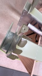

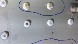
I just had an insight as I posted this image above that the mirror image bracket may not be the same - and sure enough it is not.
This is what they should look like from above.

This is the left side build per KAIs - note the elevation of the bracket relative to the hole in the rib. It is correct.

And this is the right side built without thinking through it (and not specified in the KAIs) - this is built and installed incorrectly. Well, that's a new project for this week.

This is what they should look like from above.
This is the left side build per KAIs - note the elevation of the bracket relative to the hole in the rib. It is correct.
And this is the right side built without thinking through it (and not specified in the KAIs) - this is built and installed incorrectly. Well, that's a new project for this week.
Attachments
Last edited:
The aileron counterbalance tubes came in so it was time to install them. Many thanks to the previous posters that figured lots of this out.
First step was to figure out which way the tube goes on correctly (great guidance in the RV-15 Wiki). I found it helpful to tape on the tube and then cleco the LE skin on to double check that everything lines up properly - and to know which holes to countersink. It should be dead nuts on if everything is right.
Then on to countersink the holes in the tube. It was hard to judge exactly how deep these should go, and the countersink tended to wander quite a bit because there's nothing to support it from behind. These worked OK, but I made them slightly larger for the other aileron.
View attachment 114857
My neighbor had some issue with the internal ribs creating dents through the skin, so I figured I'd sand down that part a bit. Turns out it really wasn't necessary as everything came together quite well. (Maybe he was forcing things?)
View attachment 114859
I used a single 960 washer under the screw head and the nuts went on just fine and didn't bottom out.
View attachment 114860
Additionally, some Dowsil 737 silicone (Proseal would work too) was used on the middle rib to minimize the rib vibrating on the tube. I'm not sure why this metal to metal unsecured contact is OK.
View attachment 114861
The bottom side of the LE skin laid up nicely because of the dual flat surfaces, but the top was curved so I decided to put a shallow roll along the long aft edge. It was OK without the roll, but IMO better with the roll (which takes about 2 minutes to do). Here's a picture with the rivets in.
View attachment 114864
Learning a bit from my neighbor's trials and tribulations, it worked well to cleco the LE skin as follows:
1. Cleco all along bottom long edge of the LE skin
2. Cleco up the three ribs going forward. (starting in center, then edges)
3. Push the skin around the tube and cleco the forward hole on the top front of the LE skin
4. Work your way backward and then cleco the long top aft edge.
5. Rivet per instructions.
At least for me, everything lined up nicely.
View attachment 114862
And here with the weights (which were primered and taped to isolate from the tube)
View attachment 114866
According to this galvanic reaction chart, lead and stainless steel don't play well with each other.
View attachment 114867
Two ailerons officially completed!
View attachment 114865
Great Post Thanks.
I think that a mirror view of the assembly should be included in the KAIs…just one isometric drawing would be sufficient to check you work and be assured that you are building as intended.
I think that a mirror view of the assembly should be included in the KAIs…just one isometric drawing would be sufficient to check you work and be assured that you are building as intended.
That would be great. I saved my KAI's in th opposite (right handed) view. Pics are great however they are not searchable and all numbers are backwards.
I had my printer do a mirror image of the KAI's. I put it in Section 5 of the Wiki.I think that a mirror view of the assembly should be included in the KAIs…just one isometric drawing would be sufficient to check you work and be assured that you are building as intended.
Marc,I just had an insight as I posted this image above that the mirror image bracket may not be the same - and sure enough it is not.
This is what they should look like from above.
View attachment 114884
This is the left side build per KAIs - note the elevation of the bracket relative to the hole in the rib. It is correct.
View attachment 114885
And this is the right side built without thinking through it (and not specified in the KAIs) - obviously incorrect. Well, that's a new project for this week.
View attachment 114887
Since I haven't started them yet this is probably a silly question. Why are the bushings reversed on the right side (longer on top).
And this is the right side built without thinking through it (and not specified in the KAIs) - obviously incorrect. Well, that's a new project for this week.
View attachment 114887
I made the same mistake. The inboard bell crank is symmetrical, which tricked me into thinking lazy and assuming the outboard would be too.
Drilling to separate those parts did not go great for me. Long rivets in thick material, it really didn't want to come apart around the bearing. I ended up galling the parts enough that I don't want to use them. $36 each for the bell crank halves if anyone is wondering.
The right side as shown is incorrect. It what it looks like when you build both sides the same. The bushing should have the long section on the bottom, so I have to disassemble the halves and re-do it. (like Nate)Marc,
Since I haven't started them yet this is probably a silly question. Why are the bushings reversed on the right side (longer on top).
Got it... Looking at the WIKI and reading posts like yours and others is a huge help. Really appreciate you taking the time to document your build.The right side as shown is incorrect. It what it looks like when you build both sides the same. The bushing should have the long section on the bottom, so I have to disassemble the halves and re-do it. (like Nate)
Thanks for sharing Nate. Your pain made me go slowly and carefully, and was able to reuse the parts. Quite an effort, but one step a time.I made the same mistake. The inboard bell crank is symmetrical, which tricked me into thinking lazy and assuming the outboard would be too.
Drilling to separate those parts did not go great for me. Long rivets in thick material, it really didn't want to come apart around the bearing. I ended up galling the parts enough that I don't want to use them. $36 each for the bell crank halves if anyone is wondering.

Here's what they're supposed to look correctly. They are mirror images, not identical parts:


The large part of the bearing is on the bottom side.

Last edited:


Just to clarify, the balloon is there to prevent over pressurizing the tank; the leak check should involve going over every rivet and seam with a bubble solution. I used Camco HVAC leak detection fluid on my -10 tanks as I found it works better than soap and water.With the CiES fuel sender and access covers installed, the tanks passed their pressure test.
View attachment 114985
That balloon will only show you larger leaks, and it will be difficult to factor out the temperature/pressure effects due to ambient conditions.
Great to see your progress, Marc!

They look great Marc.Flaps and ailerons are completed (including filling the rivets) and going out to the hangar for storage this weekend.
View attachment 115148
With such limited space in the shop, all the parts need to be prepped prior to starting the wings in earnest. Otherwise, there's no room to prep the parts with the wing covering both of the tables. Got a bunch of parts finished up this weekend:
Primed the rest of the wing skins and riveted on the nut plates on all the many access panels.

Finished the nut plate mounts for the wing lights. Note that the acrylic lens needs to be countersunk, although this is not called out in the KAIs.

Prepped and primed numerous misc parts for the wing:


Added the extension to the main spars, using the rivet gun. This was pretty straightforward except for the rivets just up under the curled over part of the spar rib. The angled end of the tungsten bucking bar actually worked perfectly for this. You'll notice some wood blocks around the spar. I like to have major parts fairly secure so the rivet gun does not move things around or things don't tip over accidentally. YMMV.

Finally, the small AD3 holes on the inboard edge of the wing (top and bottom) were countersunk. I noticed some of the filings were getting in the cracks between the spar components (could not get out the fine shavings), so tape was added to keep it all clean. A quick shot of primer to finish it off. The AD3 rivet shown is to verify the hole size.

Now the wing build starts...
Primed the rest of the wing skins and riveted on the nut plates on all the many access panels.
Finished the nut plate mounts for the wing lights. Note that the acrylic lens needs to be countersunk, although this is not called out in the KAIs.
Prepped and primed numerous misc parts for the wing:
Added the extension to the main spars, using the rivet gun. This was pretty straightforward except for the rivets just up under the curled over part of the spar rib. The angled end of the tungsten bucking bar actually worked perfectly for this. You'll notice some wood blocks around the spar. I like to have major parts fairly secure so the rivet gun does not move things around or things don't tip over accidentally. YMMV.
Finally, the small AD3 holes on the inboard edge of the wing (top and bottom) were countersunk. I noticed some of the filings were getting in the cracks between the spar components (could not get out the fine shavings), so tape was added to keep it all clean. A quick shot of primer to finish it off. The AD3 rivet shown is to verify the hole size.
Now the wing build starts...
Last edited:
Got the fuel tank and aft wing spar assy laid out on two tables. 36" across and 14 ft long. Substantial!

Riveting the aft spar to the fuel tank aft spar was pretty easy.

But riveting on the inboard mixer box is where things got interesting. I had to drill out about 8 Cherry Max rivets as they did not seat correctly. I tried different air pressure as well as even used an electric rivet puller. Nothing delivered consistent results. This was probably the most frustrating part of an rather enjoyable build so far.

When the Cherry Max are pulled correctly, the stem is generally flush with the head. When incorrect, the stem is usually recessed and is very obvious. You can also very from the back side, but with the mixer box design it is difficult to inspect the back side. I used an inspection mirror but it was marginal at best.


The Cherry Max are fairly easy to drill out and replace (drill of the head with a #30 bit then use a small flat punch), but I did pull one without realizing it wasn't fully seated. That cost me 1 hr+ to fix it, and I ended up bucking a solid rivet and re-priming the area. What a mess!

In the above picture, I bent down the ribs to get a straight angle into the bottom Cherry Max rivet. Then bent them back up, fluted them, and adjusted to make everything sort of line up. Still on the fence if that's the right approach for the right wing. TBD. This area is kind of a mess, really.
All done!

Adding the flap tracks was straightforward and easy.

Riveting the aft spar to the fuel tank aft spar was pretty easy.
But riveting on the inboard mixer box is where things got interesting. I had to drill out about 8 Cherry Max rivets as they did not seat correctly. I tried different air pressure as well as even used an electric rivet puller. Nothing delivered consistent results. This was probably the most frustrating part of an rather enjoyable build so far.
When the Cherry Max are pulled correctly, the stem is generally flush with the head. When incorrect, the stem is usually recessed and is very obvious. You can also very from the back side, but with the mixer box design it is difficult to inspect the back side. I used an inspection mirror but it was marginal at best.
The Cherry Max are fairly easy to drill out and replace (drill of the head with a #30 bit then use a small flat punch), but I did pull one without realizing it wasn't fully seated. That cost me 1 hr+ to fix it, and I ended up bucking a solid rivet and re-priming the area. What a mess!
In the above picture, I bent down the ribs to get a straight angle into the bottom Cherry Max rivet. Then bent them back up, fluted them, and adjusted to make everything sort of line up. Still on the fence if that's the right approach for the right wing. TBD. This area is kind of a mess, really.
All done!
Adding the flap tracks was straightforward and easy.
Attachments
Cherry actually published a specific removal process for Cherry Max rivets.
Because the stem and locking collar are fairly hard material, a drill bit can easily wander off center and potentially damage the adjacent structure.
Cherry recommends that the rivet head be ground down enough for the locking collar to be removed, and then the stem driven out with a 1/16" pin punch. I use a small cutting disk in a Dremel tool.
Once the stem is removed, it is very low risk to drill the remaining aluminum rivet body.
This assumes a fully set (locked) rivet. In the case were it is not fully set, I would still drive out the stem prior to doing and drilling.
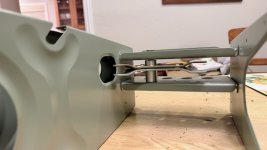
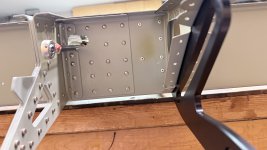
It was fun to install the aileron push tubes, with a rather ingenious way to adjust the length of the rods. Nothing too tricky here, just follow the instructions.


The un-conected ends of the rods (at wing root and aileron) were covered with padding so they would not rub or scratch against the frame.

Moving on to the main (front) spar, I saw on the WIKI that there were three rivet holes that needed rivets. These rivet (holes) are not referenced in the KAIs, as of now. I figured it would be easiest to install these rivets before installing the spar onto the wing assy. That was only partially correct.
These two rivets can be bucked prior to installing the main spar:

This one needs to be done in the right sequence (don't ask how I know):

This rivet also captures the flange on the fuel tank assy. So it must be done in this sequence:
1. Install the main spar per instructions (first step)
2. Fill the empty hole with rivet making sure it goes through to flange on fuel tank assy
3. Install rib that goes on the 5 rivet holes above, per instructions
This is not mentioned in the current KAIs.
This is the back side, showing the fuel tank flange:

Put a rivet in to secure the flange, before riveting on the nose rib:

The back side of these rivets are quite tricky to get to and place a bucking bar. A second person could be helpful here. You'll note there are six rivets. 5 for the rib, and one below it that only attached to the fuel tank.

Once the rivet is in, then install the nose rib:

Done!


The un-conected ends of the rods (at wing root and aileron) were covered with padding so they would not rub or scratch against the frame.
Moving on to the main (front) spar, I saw on the WIKI that there were three rivet holes that needed rivets. These rivet (holes) are not referenced in the KAIs, as of now. I figured it would be easiest to install these rivets before installing the spar onto the wing assy. That was only partially correct.
These two rivets can be bucked prior to installing the main spar:
This one needs to be done in the right sequence (don't ask how I know):
This rivet also captures the flange on the fuel tank assy. So it must be done in this sequence:
1. Install the main spar per instructions (first step)
2. Fill the empty hole with rivet making sure it goes through to flange on fuel tank assy
3. Install rib that goes on the 5 rivet holes above, per instructions
This is not mentioned in the current KAIs.
This is the back side, showing the fuel tank flange:
Put a rivet in to secure the flange, before riveting on the nose rib:
The back side of these rivets are quite tricky to get to and place a bucking bar. A second person could be helpful here. You'll note there are six rivets. 5 for the rib, and one below it that only attached to the fuel tank.
Once the rivet is in, then install the nose rib:
Done!
Attachments
Today was wing skin and cleco day. The wing skins and stiffeners went on easily, much easier than the -7 I built 20 years ago. I though the stiffeners might be difficult to capture with the clecos, but in fact it was all very straightforward. The downside - it requires a lot of clecos. Best estimate is about 900-1000 copper clecos. It would be nice to get some guidance from Van's on perhaps doing this in parts.

Bottom side:

Per the KAIs, start at the front and work aft. The duck tape really helpd.

Top side:


Even though I borrowed a bunch of clecos from other builders and ordered 400 new ones, this is where I ran out of clecos. 200 more on order. Most RV builders have the silver #40 clecos, but not a huge quantity of the copper #30 clecos.

Bottom side:
Per the KAIs, start at the front and work aft. The duck tape really helpd.
Top side:
Even though I borrowed a bunch of clecos from other builders and ordered 400 new ones, this is where I ran out of clecos. 200 more on order. Most RV builders have the silver #40 clecos, but not a huge quantity of the copper #30 clecos.
rvanbladeren
I'm New Here
Marc, You will note that the fifth rivet back on the top of each nose rib has it's tail blocked by the stringer making it difficult to get a bucking bar in there. So, we removed the stringer clecos and slide the stringer out one end of the wing which gave us a clear shot at the rivet tail. Then we set the one rivet on each nose rib, slide the stringer back in place, clecoed it and pressed on.Today was wing skin and cleco day. The wing skins and stiffeners went on easily, much easier than the -7 I built 20 years ago. I though the stiffeners might be difficult to capture with the clecos, but in fact it was all very straightforward. The downside - it requires a lot of clecos. Best estimate is about 900-1000 copper clecos. It would be nice to get some guidance from Van's on perhaps doing this in parts.
View attachment 116131
Bottom side:
View attachment 116132
Per the KAIs, start at the front and work aft. The duck tape really helpd.
View attachment 116133
Top side:
View attachment 116134
View attachment 116135
Even though I borrowed a bunch of clecos from other builders and ordered 400 new ones, this is where I ran out of clecos. 200 more on order. Most RV builders have the silver #40 clecos, but not a huge quantity of the copper #30 clecos.
View attachment 116136
rvanbladeren
I'm New Here
We also waited to install the landing light frame until the last two nose ribs where riveted in place. Then we installed the small 1/4 support rib. The landing light frame can then be slide in through the light opening and using pull rivets, set in place.Marc, You will note that the fifth rivet back on the top of each nose rib has it's tail blocked by the stringer making it difficult to get a bucking bar in there. So, we removed the stringer clecos and slide the stringer out one end of the wing which gave us a clear shot at the rivet tail. Then we set the one rivet on each nose rib, slide the stringer back in place, clecoed it and pressed on.
