May 25, 2026 -
Left and Right Switches Brainstorming
So the title of the post gives away the ending a little, but I fished out some of the old locking toggles I had from the other project to mess around a little with switch placement.
At this exact moment (a little foreshadowing to the end of this week), I am planning to have a two-screen Garmin display, with a few extras here and there. I think it'd be slick to have most of the switches off the actual instrument panel.
On a version of my cockpit design page, I have grouped switches into right and left hand preference (based on whether I'm holding the stick back during/after start).
Right Hand:
- Main Bus Master
- EBUS Master
- Nav Lights
- Strobe Lights
Left Hand:
- L PMAG
- R PMAG
- Starter enable
- Fuel Pump
- Pitot Heat
- Taxi Light
- Landing / Wig Wag
I figured if I could stick all the “right” switches on the lower right panel, and all the “left” switches on the lower left panel (forward of the throttle quadrant, that would just leave some of the “other” switches (discussed later) on the actual left and right instrument panel edges. The other switches being:
Upper Left:
- Smoke Enable and status LED
- Pitot Heat
- Eyeball vent
Upper Right:
- Pilot seat heat
- Dimmers (Instruments, Panel, Courtesy)
- USB power (this may be better in a more hip-proximate place, though)
That ended up with a panel that looks like this:
Pretty. Expensive. Pretty expensive, in fact.
To that end, I decided to grab the left and right panels I ordered extra from Van's (because I knew I'd want to mess around with this earlier than I should) and started laying some switch pattern's out in a way that would work.
So let's start with the right side. Without taking any real pictures, I carefully spaced out the big locking toggles so there was 1) adequate room to the left of the left switch, 2) adequate room between the right switch and the support angle, 3) enough room in front of the toggle for my big fingers to grab it and pull up and over the locking gate, and 4) enough room between the front toggles (if they were back) and the rear toggles (if they were forward). Then I drilled some holes (0.459" for the switch threads, and a 0.125" hole for the keyed washer that keeps the switches from rotating.)
I'm pretty proud of this, look below for more.
There was a lot of careful measuring and marking with a fine point sharpie.
Here are two locking toggles, installed.
From the rear, I'm happy with the spacing.
Up here's good.
And underneath the panel, here's a shot of the spacing I have with the support angle installed.
It's almost as if I measured carefully or something.
I added a third switch (but that's going to be the strobe light switch, so not important to be locking).
I spent an embarrassing amount of time actuating the switches once I got to this step.
Okay, let's measure and document the switch spacing I seem to like.
1 and 1/8" laterally.
and...
2" longitudinally.
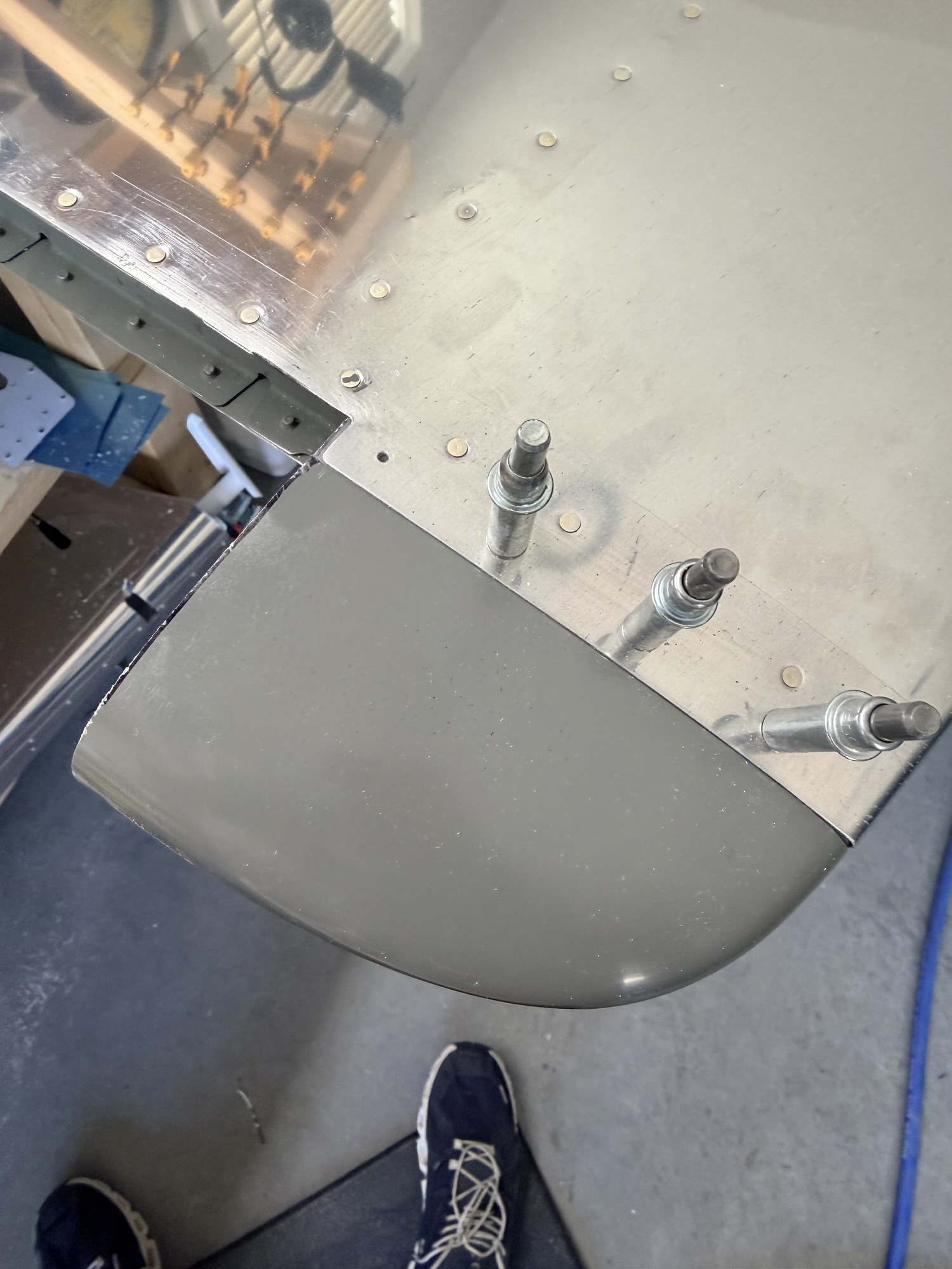
After smelling the scent of sweet victory, I delved into the left side. This area is going to be just in front of the throttle quandrant.
More foreshadowing: "Why doesn't anyone else use this real estate for switches. Seems like the perfect place..."
More measuring, more marking.
Well, shoot.
This next shot looks good, but I bet you can start to see what's happening.
The left switch fits fine, but if I put a switch in the right hole, it interferes with the nutplate that exists for that forward screw (the one that's partially backed out.)
Also, do you see the four rivet holes beneath that?
Well, that's for a builder-fabricated bracket that holds the throttle, prop, and mixture cables.
I can't put any switches here. Dang.
It does look good, but it won't work.
Anyway, I stopped here, realizing I had ruined a $6 part. (Not ruined, I bought it as an extra to mess around with.
And I did mess around, and I learned something from it. $6 well spent, if you ask me.
Homework for myself for this week: go sit in an RV-8 to figure out where I should put my "left" switches.
1.0 on the panel today.


 ) it seems not enough pressure being applied to the gun side whilst riveting, and/or the set not being fully square to the piece/rivet head. Another cause might be air pressure not properly set. Also there are many kind of tape available to apply to the set's head, I just used painters tape, cheap, easy to tear off, replaced every 3rd rivet or so, to also prevent the set end to jump off its ideal position.