Van's Air Force

The definitive Van's Aircraft support community! Buying, building or flying an RV? Join our exclusive family of mentors and enthusiasts!

LED's for Honeywell AML34 Microswitch...

bjdecker

Well Known Member
Ambassador
PIREP:
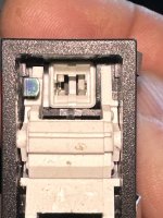
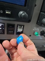
Upgraded/Replaced all the lighting modules in my AML34 switches. These new LED modules provide a much larger and lower resistance contact to the guts of the switch. I did have to "tweak" the contacts in the switch innards (think: dental pick, tiny screw driver) so the sweep would contact the lands on the module a bit better.

Dave B @ Avionics Systems recommended them and I'm liking the results so far. Thanks Dave!

From Superbright LEDs -- https://www.superbrightleds.com/74-led-bulb-3-smd-led-miniature-wedge-base+color-Natural~4000K --- probably can source them at Mouser, Digikey, etc. also.

74-led-bulb-3-smd-wide-angle-wedge-base.webp

IMG_6758.jpeg
 
I used 2 red (Batt & alt), 1 amber (Fuel pump), the White is 4000K...
4 years and 600 hrs. my AML's using dental picks and 1.5 mm screwdriver could not create enough friction to hold the contacts. Replace early or preferably before you insert an OEM bulb which is thicker than these bulbs. I tried a new AML socket and these hold the new brightlights bulb quite nicely. FYI, this is what the new bulb looks like from SBL's. Screenshot 2024-11-16 171920.jpg
 

Was hoping these would be thicker than the bulbs Stein used in my panel or at least thicker than the ones from superbrightled but the base is exactly the same thickness (1.92 mm) so no improved contact. They are slightly shorter than the ones from SBL but that should not be a factor. My old lights I was able to turn my dimmer all the way down and the bulb would still light up a little. These bulbs take about 50% on my dimmer pot to start and lite. Not a big deal if you replace all of them. Overall, a good choice if you replace early. Also apply dielectric grease to bulb contacts and especially AML back contacts, they tend to oxidize.

Also getting black caps allows one to turn it up brighter and gives less "flicker".
 
Last edited:
I have several of these switches with lights inop. What I don’t know is how to disassemble them to service the lights.
Hi John. the cap (called the Operator) just pops off with a bit of a tug. The bulb is easily removed with a set of forceps or similar tool.
 
Hi John. the cap (called the Operator) just pops off with a bit of a tug. The bulb is easily removed with a set of forceps or similar tool.
Most of mine (all but one) there is a metal lever on the side that you hook your finger nail under to pull out the bulb after you pop off the cap.

Derek
 
I have several of these switches with lights inop. What I don’t know is how to disassemble them to service the lights.
The caps pop out easily, from the top when in the off position.
The bulbs are ejected by pulling on the little tab visible on the left side of the cavity.
Once the bulb has been removed, push the white carrier back in, and then put eyes on the metal "tangs" on the upper and lower sides of the which are designed to contact the bulb. Use a dental pic or similar tool to adjust the tangs for optimal contact.

Positing some of the pictures again:

1731267222545.jpg
Screenshot 2024-11-10 at 4.58.29 PM.png


Good luck!

B
 

Attachments

  • 1731267761010.jpg
    1731267761010.jpg
    1,016.1 KB · Views: 13
On the topic of the sbl led replacements. Did anyone try adding some solder to build up the flats that don't seem to fit the socket (requiring dental picks to reshape the tangs)? I've got some coming tomorrow and I'll try them without and if they aren't making contact, I think I'll add a little solder and see if I can build them up vs bending the tangs
 
On the topic of the sbl led replacements. Did anyone try adding some solder to build up the flats that don't seem to fit the socket (requiring dental picks to reshape the tangs)? I've got some coming tomorrow and I'll try them without and if they aren't making contact, I think I'll add a little solder and see if I can build them up vs bending the tangs
See contact cross section diagram in earlier post. Solder will result in a smaller contact area than the spring-to-tinned contacts affair.
 
See contact cross section diagram in earlier post. Solder will result in a smaller contact area than the spring-to-tinned contacts affair.
Maybe I read the prior posts wrong, I thought the contacts are on the outside of the bulb leads, top and bottom and the led replacements are too thin? Meaning you have to bend the leads to make contact? Adding some solder to the led replacements to build up the thickness wouldn't solve this? It's really hard to understand what the problem is I guess without experiencing it.
 
Maybe I read the prior posts wrong, I thought the contacts are on the outside of the bulb leads, top and bottom and the led replacements are too thin? Meaning you have to bend the leads to make contact? Adding some solder to the led replacements to build up the thickness wouldn't solve this? It's really hard to understand what the problem is I guess without experiencing it.
So, I've been to this rodeo multiple times: Original filament bulbs, Stein LEDs, Other source LEDs, added solder for thickness to exert more pressure on the contacts, bending contacts, and nothing works. Light on, then randomly or when operating switch - light off. In my 12 switches there's always at least one goofing off. Does anyone out there actually understand the root cause of the problem AND have a positive fool-proof fix? I'd love to just solder the little guys in if there were sufficient access!
 
So, I've been to this rodeo multiple times: Original filament bulbs, Stein LEDs, Other source LEDs, added solder for thickness to exert more pressure on the contacts, bending contacts, and nothing works. Light on, then randomly or when operating switch - light off. In my 12 switches there's always at least one goofing off. Does anyone out there actually understand the root cause of the problem AND have a positive fool-proof fix? I'd love to just solder the little guys in if there were sufficient access!
...I guess you didn't read far enough back...
 
The caps pop out easily, from the top when in the off position.
The bulbs are ejected by pulling on the little tab visible on the left side of the cavity.
Once the bulb has been removed, push the white carrier back in, and then put eyes on the metal "tangs" on the upper and lower sides of the which are designed to contact the bulb. Use a dental pic or similar tool to adjust the tangs for optimal contact.

Positing some of the pictures again:

View attachment 78661
View attachment 78660


Good luck!

B
Well, actually did, and this is not how it works for the AML 34 switches. With either the original Honeywell filament bulbs or Stein LEDs or PCB versions, there is a substrate - i.e. the glass for filament, plastic mount for Stein, or circuit board material sandwiched in between contacts on opposite sides. For glass or Stein's, there are wire contacts only on alternate sides. Other than a snarky response, please explain. Are you talking about an entirely different bulb perhaps?
 
Well, actually did, and this is not how it works for the AML 34 switches. With either the original Honeywell filament bulbs or Stein LEDs or PCB versions, there is a substrate - i.e. the glass for filament, plastic mount for Stein, or circuit board material sandwiched in between contacts on opposite sides. For glass or Stein's, there are wire contacts only on alternate sides. Other than a snarky response, please explain. Are you talking about an entirely different bulb perhaps?
Sorry, but please explain what you mean by "putting eyes" on the contacts?

I'll try again to clarify --

The Honeywell AML34 operator has spring "sweeps" on the left and right side of the bulb socket (see closeup pic -- magenta highlights the sweeps)

1731267222545 (1).png

If you use the Chicago Miniature CML73 T1.75 bulb in the socket, the leads (wires) of the bulb are in contact with one of the "sweeps" on each side of the socket. This is fine, as the CML73 is purely resistive and mostly insensitive to voltage drop. (gratuitous picture of CML73)

_W2X4.6D_T1.5v2__58627.jpg

All good so far -- but these little CML bulbs aren't great in high vibration environments; the filament breaks/they burn out over time, etc. So let's use LED versions of the bulb.

Initially, I used an LED wedge bulb 74 form factor. (pic)

74-whp0.webp

After a time they would flicker. Because the "sweep" to "wire" contact area is so small (pic) and not gas tight, it develops an oxidation layer due to moisture in the air and vibration along the contact area. This leads to an increase in resistance, which causes a voltage drop, which interrupts current flow, which causes the LED to flicker.

Screenshot 2024-11-10 at 4.58.29 PM.png

The PCB version of the LED 74 bulb is superior to the Wedge bulb because the contact area is much larger.

74-led-bulb-3-smd-wide-angle-wedge-base.webp

When inserting the PCB version into the socket, I noticed that there was a bit of interference, which would cause the leading edge of the "sweep" to bend back up and away from the PCB contact area.

This is what I meant by "put your eyes on" -- get a magnifying glass, or smartphone camera in macro mode, to visually inspect the "sweeps" -- fix them as appropriate with a dental pick, small screwdriver, tool appropriate to the task, to bend the sweep ramp to make contact correctly.

FWIW - PCB LEDs have been functioning perfectly since the change over and sweep adjustment - no flicker, no flash.

IMG_6759.jpeg


Sorry about the snark...
 
Excellent! Thanks! I've ordered some of the PCB LED versions. Assume they also have contacts on both sides which should also help.
 
On flickering; -- flight yesterday I noticed that the STROBE light was flickering a little bit. I took the unit apart to see what was happening.

During the changeover to the PCB LED modules, the top left side "sweep" caught the edge of the PCB and was bent all the way back into the cavity. This caused a very intermittent contact -> flickering with vibration from the engine running.

In the AML34, both sides Left:Right & Top:Bottom of the sweeps need to make contact with the bulb.

Picture for reference. I will fix this with a dental pic to similar...

1762284419177.jpg

@N49ex Very good idea on beveling the edge of the PCB board -- it would have prevented this problem.
 
On flickering; -- flight yesterday I noticed that the STROBE light was flickering a little bit. I took the unit apart to see what was happening.

During the changeover to the PCB LED modules, the top left side "sweep" caught the edge of the PCB and was bent all the way back into the cavity. This caused a very intermittent contact -> flickering with vibration from the engine running.

In the AML34, both sides Left:Right & Top:Bottom of the sweeps need to make contact with the bulb.

Picture for reference. I will fix this with a dental pic to similar...


@N49ex Very good idea on beveling the edge of the PCB board -- it would have prevented this problem.
This is a real problem with these PCB LED's and you don't know it's happened until the damage is done. Once bent, I have found it extremely difficult to straighten the pins again. It's very easy to break the contacts off trying to get them back into place once pushed back. They also seem to lose their springiness. All in all, it's a pretty crappy design for a $100 switch.
 
This is a real problem with these PCB LED's and you don't know it's happened until the damage is done. Once bent, I have found it extremely difficult to straighten the pins again. It's very easy to break the contacts off trying to get them back into place once pushed back. They also seem to lose their springiness. All in all, it's a pretty crappy design for a $100 switch.
I don't think the AML design ever considered the use of PCB LEDs. The original CML 73 bulbs have a generous and smooth "lead in" for the bulb; no edge to catch.
 
I don't think the AML design ever considered the use of PCB LEDs. The original CML 73 bulbs have a generous and smooth "lead in" for the bulb; no edge to catch.
True. I also don't think both top and bottom contacts need to make contact with the PCB, so you shouldn't have to bend the contact back. So long as one contact is touching the PCB, the LED should light. But polarity matters, of course.
 
True. I also don't think both top and bottom contacts need to make contact with the PCB, so you shouldn't have to bend the contact back. So long as one contact is touching the PCB, the LED should light. But polarity matters, of course.
....and this is where my flicker came from; the ground side "sweep" (left side of my switch) only contacted the bottom PCB trace. The + / power side sweeps were in contact on both top/bottom... To your point, not enough force applied with only one sweep -- add a little vibration and Voila! Flickering...
 
Back
Top