I've started work on the stein wiring harness for the panel, and sub panel, and there isn't much out there in a single thread, so starting this thread for more discussion and ideas on sub panel mounting. Ideas, comments, "show us your" sub panel type thought for this thread. Everyone has different avionics, but starting to be more G3X and remote mount avionics probably in the majority, and need a spot to talk about it.

Van's Air Force
You are using an out of date browser. It may not display this or other websites correctly.
You should upgrade or use an alternative browser.
You should upgrade or use an alternative browser.
Show us your sub panel installation and ideas RV 14
- Thread starter lipper03
- Start date

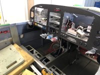
Maybe this will help. I did my own wiring (using everything bought from Stein), all Garmin stuff plus VPX Pro. Everything has worked out great except my only regret was not putting in longer service loops on each harness. i thought I was doing enough but I should have had more. The harnesses are not as "clean" as what you would get from Stein but everything worked correctly from first power up, and no issues 40+ hours in.

Last edited by a moderator:
My stein air design for the harness and rough locations. Looks simple enough, but need to mount adel clamps for the harness and the boxes on the sub panel, and boxes in between panel and sub panel, as well as a VPX in front of the sub panel.

A few ideas from the interwebs:
This one from a leaf in the wind on YouTube building a RV10 YouTube
This one from Jetshine building a sling 4 link
I really like the hat's from Jetshine, and I've started a design for one for the GTX 45R and GMA245R shelf.
Using the standard aircraft handbook, making a 0.5" flange x 2" high x 6.3" wide (for the 45R cage) x 9" long. I've got a Total length of 10.508" x 9" to cut and mark the tangent lines and the sight lines. It took me a few tries on paper to visualize the different charts and calcs, but all that to get the right bend allowance and variance for having 90 degree bends in metal. I have a brake coming to get a test piece done, and I'll get that posted as well.
A few ideas from the interwebs:
This one from
a leaf in the wind on YouTube building a RV10 YouTubeThis one from
Jetshine building a sling 4 linkI really like the hat's from Jetshine, and I've started a design for one for the GTX 45R and GMA245R shelf.
Using the standard aircraft handbook, making a 0.5" flange x 2" high x 6.3" wide (for the 45R cage) x 9" long. I've got a Total length of 10.508" x 9" to cut and mark the tangent lines and the sight lines. It took me a few tries on paper to visualize the different charts and calcs, but all that to get the right bend allowance and variance for having 90 degree bends in metal. I have a brake coming to get a test piece done, and I'll get that posted as well.
This is great! Need more folks to post, and post some of the details, like the mounts for the VPX and other boxes. Did you use angle, mounted on top of flanges, bottom, etc.Maybe this will help. I did my own wiring (using everything bought from Stein), all Garmin stuff plus VPX Pro. Everything has worked out great except my only regret was not putting in longer service loops on each harness. i thought I was doing enough but I should have had more. The harnesses are not as "clean" as what you would get from Stein but everything worked correctly from first power up, and no issues 40+ hours in.
View attachment 74924
Here's other's I've found. If I give the wrong credit, let me know and I'll fix.
 Luis's RV14 blog
 Justin's RV10 blog
 Scott's RV14 blog
Luis's RV14 blog Justin's RV10 blog Scott's RV14 blog


Give your bundle runs in the tunnel some thought. Van’s has provided locations for various things ( well thought out). I’m repairing an RV-14A and the runs in the tunnel leave a lot to be desired.
The builder added items ( antenna cables, pitot static tubes, etc) and elected not to install snap bushings in the spars because there wasn’t space for them. There are small holes to the side for pitot tubes, and antenna cables.
Take your time and research your runs.
The builder added items ( antenna cables, pitot static tubes, etc) and elected not to install snap bushings in the spars because there wasn’t space for them. There are small holes to the side for pitot tubes, and antenna cables.
Take your time and research your runs.
Nice, unfortunately from post #2, the design I got from stein does not work, interfering equipment, so having to figure it out.Steinair provided recommended subpanel population diagrams to go along with the RV-14A panel that they did for me.
View attachment 75133 View attachment 75134
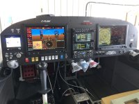
Which I was successfully able to build to
View attachment 75135
and has been a delight to fly behind ever since
View attachment 75137
Great advise, reason why I’m working on this now, learn where and what needs to be looked at harder and get solved.Give your bundle runs in the tunnel some thought. Van’s has provided locations for various things ( well thought out). I’m repairing an RV-14A and the runs in the tunnel leave a lot to be desired.
The builder added items ( antenna cables, pitot static tubes, etc) and elected not to install snap bushings in the spars because there wasn’t space for them. There are small holes to the side for pitot tubes, and antenna cables.
Take your time and research your runs.
Brian, Do you have the twin access panels installed in your RV, giving you access to behind the firewall ? If not, I would highly recommend. Greatly increases your options and ability to inspect what is there. I originally was not going to do this mod, but after seeing on a friend’s build it became a top priority. So glad I did it.


Yes I put the access panels in after seeing another RV14 with them, they are necessary for a QB fuse, like mine, many things they have been used for so far besides avionics.Brian, Do you have the twin access panels installed in your RV, giving you access to behind the firewall ? If not, I would highly recommend. Greatly increases your options and ability to inspect what is there. I originally was not going to do this mod, but after seeing on a friend’s build it became a top priority. So glad I did it.
George, what did you use in the map box to mount those boxes? Maybe a picture from underneath? Looks like my GMA245R is going there.
We built a little tray out of sheet and J stiffeners. Yeah the 245 and GAD29 live thereGeorge, what did you use in the map box to mount those boxes? Maybe a picture from underneath? Looks like my GMA245R is going there.

I bet money that anyone who has built a 14 without these access hatches either has regretted it deeply, or will regret it deeply some day.Yes I put the access panels in after seeing another RV14 with them, they are necessary for a QB fuse, like mine, many things they have been used for so far besides avionics.
")
With the canopy frame closed, trace the underside onto the sub panel aft face.This will end up a great reference

This is great advice. I didn't and made at least one mistake that needed moving.With the canopy frame closed, trace the underside onto the sub panel aft face.
View attachment 75206
Todd, that is beautiful work!With the canopy frame closed, trace the underside onto the sub panel aft face.
b,d
Finished a test of the hat shelf for the GTX45R/GAD29. I did cut some vent holes traced from the 45R tray, not sure if that's needed or not, but I figured might as well.
3D model showing "installed" and the real life shelf with the GTX45R trey cleceo'd in place.
Planning a piano hinge on the subpanel bottom flange, a .032 sheet across to two or three nutplates on the panel bottom flange.
I haven't decided on what to mount the hat to the bottom sheet with, rivets, or nutplates, or screws/nuts.

Lots of great pictures from the top, what about harness mounting? (i.e. Pictures from the bottom)
Here is an idea, but I don't know if I should do the horizontal (red) or vertical (green) mount here.
View attachment 75282


I see, you put the harness under the control cables, I'll have to play with that as well! Thanks!


Make sure you leave clearance for the canopy frame.Made a hat shelf for the GDL51R yesterday. Seems to fit pretty good!
View attachment 76454
View attachment 76453View attachment 76452
I used post #21 to get a rough distance, and put that in the fusion 3d model to check, but I'll get out C-01402R&L to trace just in case.Make sure you leave clearance for the canopy frame.
Lines drawn, they are conservative (ie they are a bit further down then actual fit), as I put the C-01402R&L just under the frame, and then I got out the hinge (C-01412) and connectors (C-01413), and confirmed the C-01402R&L sits a little higher, so looks like we have a fit, close, but good.I used post #21 to get a rough distance, and put that in the fusion 3d model to check, but I'll get out C-01402R&L to trace just in case.


Last edited:
can you flip the gtr20 radio 180 so the wire bundle will drain water and keep the wire from interfering?Lines drawn, they are conservative (ie they are a bit further down then actual fit), as I put the C-01402R&L just under the frame, and then I got out the hinge (C-01412) and connectors (C-01413), and confirmed the C-01402R&L sits a little higher, so looks like we have a fit, close, but good.
View attachment 76464 View attachment 76465 View attachment 76470
I could, but I think that limits access to the connectors only from underneath, and I think a tougher route for the comm coax. The wire bundle will be routed down in the current test configuration.can you flip the gtr20 radio 180 so the wire bundle will drain water and keep the wire from interfering?
Made a hat shelf for the GDL51R yesterday. Seems to fit pretty good!
View attachment 76454
View attachment 76453View attachment 76452
GDL51R has a built-in attitude sensor, and thus have specific orientation requirements:
From the installation manual:
- Mount the unit with the FWD arrow aligned to within 3.0° of the longitudinal axis of the aircraft (LED bezel parallel to the wing spar).
- Mount the GDL 5XR so the connectors point in the aft direction.
Thanks, I missed that, well, back to figuring out where to put it.GDL51R has a built-in attitude sensor, and thus have specific orientation requirements:
From the installation manual:
- Mount the unit with the FWD arrow aligned to within 3.0° of the longitudinal axis of the aircraft (LED bezel parallel to the wing spar).
- Mount the GDL 5XR so the connectors point in the aft direction.
Well I did find that section 2.12, I'll need to do a better job with all the relevant sections, as I was looking at section 3.5 and appendix A.GDL51R has a built-in attitude sensor, and thus have specific orientation requirements:
From the installation manual:
- Mount the unit with the FWD arrow aligned to within 3.0° of the longitudinal axis of the aircraft (LED bezel parallel to the wing spar).
- Mount the GDL 5XR so the connectors point in the aft direction.
So here is a new 3d layout, with the GDL51R moved to the almost horizontal position in front of the subpanel. Hat shelf is a different size now and I'll have to extend the two horizontal angles as well.

And a snapshot of section 2.12, mounting requirements.

Well I did find that section 2.12, I'll need to do a better job with all the relevant sections, as I was looking at section 3.5 and appendix A.
So here is a new 3d layout, with the GDL51R moved to the almost horizontal position in front of the subpanel. Hat shelf is a different size now and I'll have to extend the two horizontal angles as well.
View attachment 76595
And a snapshot of section 2.12, mounting requirements.
View attachment 76596
It will not be easy to reach things there behind the subpanel.
A nice option would be to use https://advancedpanel.store/products/rv-14-map-box-ribs-pair to stack audio panel (you already have it there, probably mounted in some other way) and transponder on top of it. In this setup, both can be easily pulled out through the panel opening once you unscrew the right GDU.
Since transponder is longer than the audio panel, back connectors on both will be accessible from below. Also, the space behind the transponder in this setup leaves sufficient space to place the ground block there on the back side of the firewall.
GDL can then be mounted on the small removable rails between the panel and subpanel on the passenger side (the space for some reason is frequently used to mount a huge transponder that honestly barely fits there) - this will ensure the proper GDL orientation.
The only stretching I had to do while installing things this way on my build was to screw transponder/audio trays to the ribs. Even riveting ribs to the firewall was a one person job.
Last edited:
The GDL harness is on the left side, so can't move it to the right, but thanks for the idea!It will not be easy to reach things there behind the subpanel.
A nice option would be to use https://advancedpanel.store/products/rv-14-map-box-ribs-pair to stack audio panel (the you already have it there, probably mounted in some other way) and transponder on top of it. In this setup, both can be easily pulled out through the panel opening once you unscrew the right GDU.
Since transponder is longer than the audio panel, back connectors on both will be accessible from below. Also, the space behind the transponder in this setup leaves sufficient space to place the ground block there on the back side of the firewall.
GDL can then be mounted on the small removable rails between the panel and subpanel on the passenger side (the space for some reason is frequently used to mount a huge transponder that honestly barely fits there) - this will ensure the proper GDL orientation.
The only stretching I had to do while installing things this way on my build was to screw transponder/audio trays to the ribs. Even riveting ribs to the firewall was a one person job.
For anyone using those, they should consider alternatives. I’m only using it for XM receiving.
And also for Aera 796/795, 760, and the 660. It’s too bad the capabilities of the GDL will be limited by its installation.
I have done a design for the GDL fwd (in an "approved" orientation), flipped the GEA upside down (so looks like I just have to use some offset mounts instead of a hat shelf), and moved the remote audio to the extended VPX rails (instead of making something off the glove box). Also the flyled control box is now under the IBBS.
I've extended the VPX rails basically all the way across. I don't know if this will induce a vibration or not. My fusion skills aren't quite ready to model the whole front to design any attachments to the longerons (looks like it might be a piece of angle from the subpanel bottom flange to the firewall on the left side and extending the audio panel rail on the far right side), but I'm going to work on that. If anyone has any ideas, let me know.


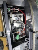
In real life, the VPX rails (test version, using 1/4" angle instead of 1") are taking form.

Also in real life the GTX45 box and hat mount for the GAD 29

I've extended the VPX rails basically all the way across. I don't know if this will induce a vibration or not. My fusion skills aren't quite ready to model the whole front to design any attachments to the longerons (looks like it might be a piece of angle from the subpanel bottom flange to the firewall on the left side and extending the audio panel rail on the far right side), but I'm going to work on that. If anyone has any ideas, let me know.
In real life, the VPX rails (test version, using 1/4" angle instead of 1") are taking form.
Also in real life the GTX45 box and hat mount for the GAD 29

DonJr
Active Member
I recommend that you do some serious reconsideration on how you will service anything behind your subpanel once you have fitted the forward upper skin behind the firewall. You have the option to add a couple service panels on the upper skin that offer you limited access at best to anything you have shown installed above. Trust me, you will not like this layout once completed if anything fails or needs servicing.I test fit angle from firewall to subpanel as an additional support for the "wings" of the VPX rails. This should eliminate any vibration concerns.
View attachment 76950
Do you have a picture of what you are doing? Ideas are welcome.I recommend that you do some serious reconsideration on how you will service anything behind your subpanel once you have fitted the forward upper skin behind the firewall. You have the option to add a couple service panels on the upper skin that offer you limited access at best to anything you have shown installed above. Trust me, you will not like this layout once completed if anything fails or needs servicing.
DonJr
Active Member
Sorry but I don't have a good picture of my current configuration. But to let you know, I did mount my TCW IBBS backup battery in the glove box area and it is a nuisance getting too if I had to remove. The TCW IBBS connector is located in the glove box opening and is accessible. The small access holes located on top to the forward skin (if installed) offer an access point, but it is still awkward getting to the battery if you needed to uninstall or use to access that area. Unless you are mounting items directly in the center area behind the radio stack, anything will be troublesome. Routing wires or even accessing wire harnesses would be very awkward in your layout in my humble opinion unless your items were mounted upside down so that you could service from the bottom cabin area. But then you have to deal with the peddles. Accessibility is the key issue in my humble opinion. Good luck with your build.Do you have a picture of what you are doing? Ideas are welcome.
My approach when I built the 10 was to wait until things were closed up before doing the mounting and installs. My logic was that if I could install it that way then I could service it later. Seemed like a good idea at the time but I did spend a lot of time working under the panel to get everything fitting nicely.
This go around on the 14, I plan to do any mounting system done prior to closing up, and I also plan to install the OP-43 access panels for future servicing. Not having the fuselage in front of me I'm guessing I could do a rail mount system and/or mount on the subpanel so both sides are accessible if need be. Or like in my 10 if I pull a G3X or panel I can get back there too.
This go around on the 14, I plan to do any mounting system done prior to closing up, and I also plan to install the OP-43 access panels for future servicing. Not having the fuselage in front of me I'm guessing I could do a rail mount system and/or mount on the subpanel so both sides are accessible if need be. Or like in my 10 if I pull a G3X or panel I can get back there too.
mountainride
Well Known Member
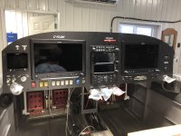
This is my second time wiring an RV-14 and I really tried to make it as serviceable as possible in the future. I built the harness on the bench, it can be removed from the aircraft in 15 minutes for any future maintenance or modification. All of my avionics are forward of the sub-panel and can be accessed from outside the airplane. I never had to get inside the airplane or under the dash for the install.

Harness laid out on bench

G3x, VPX, GEA24, GAD 29, GSU 25, Voltage Stabilizer, FlyLeds Strobe Controller

Gnx375, GMC507, G5, 2x Cannon Plug connect to the fuselage harness and molex carries higher current appliances

GMA245r, 2x GTR20. Wires for a second g3x but I prefer the ipad in a Guardian Avionics mount running foreflight

with wiring harness installed

with wiring harness installed
Harness laid out on bench
G3x, VPX, GEA24, GAD 29, GSU 25, Voltage Stabilizer, FlyLeds Strobe Controller
Gnx375, GMC507, G5, 2x Cannon Plug connect to the fuselage harness and molex carries higher current appliances
GMA245r, 2x GTR20. Wires for a second g3x but I prefer the ipad in a Guardian Avionics mount running foreflight
with wiring harness installed
with wiring harness installed
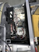
Continued work on the VPX rail mount system.
At this point I'm not sure I'm going to put any additional bracing (the 1" angle is quite stiff), as the fit isn't flush on the subpanel bottom flange or the firewall c channel (to run an angle from the subpanel to the firewall).
I am thinking of reinforcing the 4 attachment points with a 0.5" angle ran with the flange on the forward subpanel/canopy strut attach, and putting nut plates on top of the angle, so the whole thing can be removed from the bottom.
I didn't get a great shot of the remote comm, as it's on the right side of the VPX, and this picture on the bench was before I put that on. I've done a quick update of the fusion model, but haven't changed the angle on the GDL side (that's now 0.5" not 1", and the hat boxes are not shown.
The orientation of the gdl 51r only matters if you plan to use it as yet another gps. I just use mine for satellite radio and mounted it like yours. I have 4 other gps units (2 G3x 460s, 650, and a G5).Thanks, I missed that, well, back to figuring out where to put it.
Last edited:
Would you please send me this 360 file. I am trying to install all this stuff nowFound the vans 3d file, and the Garmin 3d files, and in Fusion made a few simple blocks (IBBS, VPX, CO monitor) to play with locations in the virtual world.View attachment 75016
