CAN bus...
Thanks Brian!


CAN bus...

I received my G5 ordered at OSH 2016 and have gone back and forth of what type of GPS to use to send signal to the G5 over RS232.
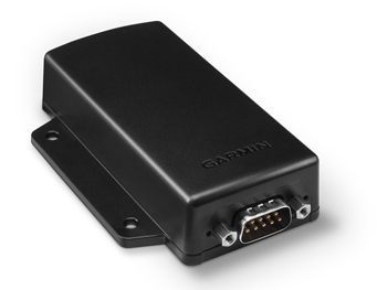
Here is one scenario. Will this "serial data passthrough" feature of my Garmin 696 work when going through the GDL 39 3D as depicted? The same signal line would feed the GTR 200 in parallel.
And out of curiosity would the GDL 39 3D show attitude on the GPSMAP 696 through the "Garmin Data Transfer" protocol?
Jim
Even if you don't have it in a G3X system, you may directly connect portable GPS units (using NMEA Out), GNS/GTN units (Aviation Out), and even SL30 and GNC255 NAV radios to the G5 RS-232 port to provide navigation information to the G5.
")
Of course, both G5's have internal WAAS GPS so you will probably want some kind of portable navigator like the Garmin 660 which will give you enroute GPS (no approaches), and I would try to pick up a GA 26C antenna on eBay for around $50 or so (for the G5) to enhance your attitude and enroute GPS.
Steve I have a G5 installed and am trying to set the V speeds and airspeed colored tape. Can you tell me were I would configure these. I looked in the
configuration page and didn't see any option.
Bill
You would need to have another instrument or use the dreaded whiskey compass.
The one dissapointment:
- No ability to connect a magnatometer to get magnetic heading without using in conjunction with a G3. One part of a true 6-pack replacement that is missing. If you are flying into a class B/C airspace and the controller vectors you, it is magnetic heading not track. You would need to have another instrument or use the dreaded whiskey compass. I would have like to get a second G5 and use as an HSI, tied with a GPS navigator to enable basic instrument capability. Although I have no intention of flying IFR, it would be nice to have the capability for that rare occasion where I might need it. This is one capability, I would like to see them add to it (hope the Garmin guys are listening!).
I have a G5 that is driven by a 430W using the #2 serial port. Both units are set to MAPMX format. The lateral deviation indicator works fine but it never displays the vertical indicator. The software version in the 430W is about 5 years old. Could that be the problem?


Hello Tommy,
The MapMX RS-232 output from your GNS 430W provides sufficient information for VFR navigation only, and does not contain vertical deviation information. For full lateral/vertical navigation display with IFR CDI scaling and annunciations, you would need to install the GAD 29 ARINC 429 adapter unit, as is shown in Figure 1-36 of the current G5 Manual (rev C).
If you do already have the GAD 29 installed and configured correctly, the most common reason to not see vertical deviation information during an LPV or LNAV+V approach is that the ARINC 429 label for vertical deviation is not enabled on the GNS 430W. To check this, make sure the "VNAV" setting on the GNS 430W ARINC 429 output configuration page is set to "Enable Labels".
- Matt
I have a 430W feeding data via ARINC 429 into my Dynon screens for the indication and coupling to the autopilot, and I have a G5 in the panel for a backup to the Dynon. Can I feed the G5 the ARINC data as well to display the lateral/vertical there also?
Hello Greg,
Yes, the ARINC 429 outputs from your GPS can be connected to both the GAD 29 and to another device.
- Matt
So I can use one of the transmit pairs on the Arinc 429 to feed back to the 430W (or is that even needed? The 430W does not take direction from external sources, right?) and the other pair to feed the G5, correct?
My understanding is that they are essentially the same unit however in the certified world the G5 can only be a primary instrument for attitude and play as secondary for other instruments such as airspeed. So in the certified world you can only replace the attitude/horizon indicator but have to leave other instruments in the panel. In the Experimental world you can use the G5 for the entire 6 pack if you choose to while flying VFR. IFR gets a bit more complicated but I don't think you were asking about that. I was told by one of the Garmin guys that essentially the guts are the same but used for different missions between certified and experimental markets.
Your signature states Munich.
Unless you have any special German exceptions, my understanding is that we in EASA for a normal class aircraft are not allowed to install a fixed instrument even if you do not plan to formaly use it without it being approved or STCd. so for a normal class AC your only option is the limited but with STC, G5 version.
Thanks for your answers. Understand now the G5 STC version has less functionality as the experimental.
But what I do not understand is how uncertified engine monitors like J.P. instruments can be built in a certified aircraft without any STC?
From EASA someone has told me that it is possible in a addition to a single cylinder EGT/CHT gauge to have a engine monitor system installed in the aircraft without an STC.
So where is the difference, keeping the six pack and adding a non STC G5 in a certified aircraft just for backup reasons?
Saw this post about a CanBus short taking out the PFD/MFD. I wondered if the same would happen to a CanBus connected G5.
If the RS-232 connections are used, does this eliminate or mitigate this failure scenario?
I'm using a G5 in our new G3X touch panel and a neighbor is adding a G5 in place of a D-10 on his legacy G3X panel - so we both wondered what would happen to our displays and G5 in the event of a CanBus failure.
Sorry if this has been asked before.
In the G5 manual it clearly states the G5 is suitable for EITHER 14V DC OR 28V DC. Does this mean as it is written 14V OR 28V
Or is somewhere in between acceptable like the Dynon & MGL where 10V-30V range is acceptable ?
I'm not trying to light a hot seat , just trying to understand how critical the voltage tolerance and what the acceptable range for the G5 is.
Thanks in Advance
This Saturday I finally got up in the air with my now G5 equipped Cozy3.
The wind gusty at around 19 knots but I still managed to perform my planned GPS triangulation flight to verify the airspeed part of the instrument. There is a 4 knots mismatch between the old instrument and the G5. After reviewing the G5 logs and using a spreadsheet I found here on the forum I feel confident in saying that my G5 airspeed indication is within one knot when running at 145kt indicated @ 2000feet, ISA -9 (QNH 1021).
One question regarding the logs, I found and tried an old 2012 G3X to .kml converter but using it for the G5 logs produces a file with almost no content. Is there a .kml(google earth) converter for the G5 logs?
Now I just need to convince the other owners to invest in a 660 and AP servos and controls
I see reference to a certified version of the G5 HSI with a magntomiter for magnetic heading. Is this something coming to us none certified people? As an add on? If so when and at what cost?
- No ability to connect a magnatometer to get magnetic heading without using in conjunction with a G3. One part of a true 6-pack replacement that is missing.
Zem
I understand the G3x has some sort of calibration/verification procedure with the GMU11 installed. I am not finding such a post-installation checkout in G5 literature or in scanning G5 menus. I wonder how magnetic disturbances are detected/handled.
Hello Chris,
You are not giving us much to go on here by not identifying which manual you are using and which software version you are using.
Page 80 of the Rev. E G5 installation manual explains the magnetic interference test.
You will want to install the current V3.20 G5 software. If your G5 software is very old it won't even know what a GMU 11 is.
Thanks,
Steve
I see the problem. I have an old version on the manual.
(Software is 3.20)
thanks,
Chris
Thanks, Steve.
One last question concerning the GTX 327 receiving RS232 data from the G5 instrument. You say to set the G5 serial port out (pin 5) to ALTITUDE ENCODER format. What should the GTX 327 serial data in (pin 19) be set to within the GTX RS232 INPUT Menu Page to use the G5 altitude encoding? GPS? ICARUS ALT? SHADIN ALT? REMOTE? Also, it looks like I can pass the same altitude data through the GTX to another device with the the GTX RS232 OUTPUT Menu Page.
Also, should there be a signal ground on the serial signal circuit wire from the G5 to the GTX or the GPSMAP 696 to GTR200? Maybe just a shield grounded on one end or both?
Thanks again. Based on our answers to my first set of questions in the last post I am proceeding with the GMC 307 and GSA 28's.
Jim

