Thanks
CF86301,
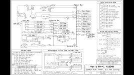
Thank you for the thorough review of my wire diagram. I know that took some time on your part, but it's exactly the information I need.
I did post an updated diagram this morning which covers a couple things you mentioned. I will continue to update as I get smarter on the subject.
(I can't reply to your comments right now, but will add this place holder and get to it when I get some time.)
Thanks again.
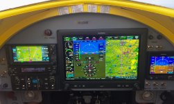
1. The left display (PFD1) and other Garmin devices required for engine instruments during start are not on the Main Power Bus. Therefore, they will not be powered at all from ships battery during start with BAT/ESNTL switch in the BAT position and Avionics switch off. During start, with the STBY BATT for PFD 1 "on", these devices should be fully powered by STBY BATT 1 to enable all necessary engine gauges. The right display (PFD2) is on the Main Power Bus so it will also be powered for start (it may or may not brown out). I didn't really want PFD 2 on the main power bus but wanted to reduce amps from the Avionics/Essential Bus. After engine start, Avionics switch (and Pri Alt switch) will be placed on, and the b/u batt will no longer be providing power and go into charge mode.
(Note: I attached STBY Batteries wire diagram for review)
2. Good point. To clarify my diagram I need to show wire sizing used for each device to justify the C.B sizes listed. I have that information in other diagrams and will add when I get a chance.
3. The Hot Battery bus. Started simple enough. Primarily needed to free up some space on the main C.B. panel. First added a couple interior convenience lights, then thought it would be a good place for the AV-30, etc. It wasn't really designed for the requirement of landing at night with BATT/ESSNTL switch off as you interpreted. I know it kind of looks that way. If it gets to that point I'm having a really bad day, ..and yes as you mentioned, I will be using the Av-30 to keep the greasy side down and the IPAD to navigate. All the items on this bus will be controlled by Honeywell AML 34 rocker switches. (except the hobbs which, after further review, will probably need to move back to Main Power Bus). Yes. The devices on this bus will run the battery down if the switches are left on. That's what checklists are for, and hopefully I will see the Nav and landing Lts on during postflight.
")
4. Yes. CB sizes will be based on wire size. Wire size will be based on loads, length, etc. If it's close, I round up on wire size and down on CB size.
5. Yes. Other than the avionics, all devices will be controlled by Honeywell AML34 rocker switches. I will try and add a picture of my layout.
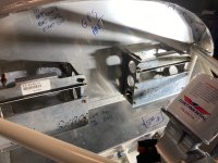
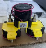
6. I moved the FLWs close to current source as you suggested. Some FLWs I removed and changed to CBs. Regarding ANL placements; I placed (not physically yet) the ANLs close to the contactors based on what I observed from the diagrams in the AeroElectric Connection. As an example, diagram Z-12 shows ANL placement for the Main Alt near the start contactor with note that states 6" or less. Also a reference to note 10 which says "consider installing a current limiter as close as possible to the starter contactor and wired per the Z-figures". I could be interpreting this incorrectly. My current design has the current limiters connected to the battery and start contactors using copper bars. This can be revised if needed.
7. I have 2 of these per wing. 14awg supply wires currently in place. Data sheet shows 1 amp/light. May have nuisance trips on the 5amp CB.
https://flywat.com/products/7168501?_pos=1&_sid=bec4bb4e5&_ss=r
8. Updated diagram (post 61) to add diode...your pushing the limit of my autocad skills now.
Those diodes come "pre-made" with the RV14. You just have to put them on the correct studs on the contactor. Mine are installed. Good catch!
9. My proposed setup of of leaving the Stby Alt switched OFF until needed seems to be getting mostly negative reviews. Most ask why not just have it switched on and ready to pick up the load in case of Pri Alt failure. Here's my thoughts (for the moment)..I'm flying along, I get a Low Volt CAS msg on the G3X display and my panel mounted annunciator light, I verify the low voltage, take a minute..maybe two, and see if there's an obvious reason it failed..smoke? circuit breaker panel glowing?..a thud and I see the Pri Alt belt across the leading edge of the wing?, etc, I check amp loading to verify within STBY Alt limits, if not maybe load shed..in my set up BATT/ESNTL switch to ESNTL would be the quickest way to accomplish that, and finally..PRI ALT/STBY ALT switch to STBY ALT - ON.
A couple things I'm not sure of: If system amp load is 25 amps (I'm guessing here), how much battery juice gets sucked out during my 1-2 minute troubleshooting. Will it cause too much initial load on the stby alt when I switch it on? I need to do the math on that...when I figure out how to do the math.
I'm sure there are other negative issues that I'm not considering and I'd like to hear them. Probably some issues with having the Stby Alt activate automatically too though.
10. Regarding the diode. I wanted to have the GTN650 on it's own STBY Batt (STBY BATT 2). It has Com, Nav, GPS capabilities. It doesn't have b/u power input pins like some of the other garmin devices (see devices on STBY BATT 1), I opted to put it on its own bus and have the stby bat feed that bus. The IBBS does have a function, I think called "pass through power", that would possibly work. However, after an email with garmin, it seemed a better approach would be to feed the buss the GTN is on. Garmin had nothing to do with the design I arrived at, and I could have mis-interpreted their email, so further research is required before I go to production. Back to the diode you mentioned.. , the diode is there so STBY Batt 2 only powers the GTN650Xi. Probably giving me around 45 mins of power. Again, I could be missing the big picture here and would like to hear other opinions on this set up.
(UPDATE 2/7/22: My interconnect wiring between STBY BATT 2 and the GTN650 is not correct. After consulting TCW, they have advised me of the preferred connection method. I will be updating my diagram and re-post when it is corrected.)
All this seems like I'm aiming for several layers of redundancy, that's not really my intention. I don't "plan" (most pilots don't) on flying in situations where there is no Plan B. However, I feel I need to design a system for that one night I make the decision to descend from VFR into a layer, lets say 4 thousand ft thick, and shoot an approach to my personal minimums. Halfway through the layer, the cabin starts filling with smoke (smells electrical). To me, the fastest way to possibly stop the smoke is switch alternator switch - off (with my setup that's one switch
), and battery switch - off. At that point both my STBY Batts activate and I finish the approach. If smoke continues, STBY Bat 1 and 2 switches are switched off, and I'm left with AV-30 and Ipad. Wish me luck.
11. Current plan is to use this
https://www.audioauthority.com/blog/16 I will need to decide which side of the battery contactor to make the connection. Seems like pros and cons to each option.
12.Thank you for your inputs!
STBY Batteries interconnect diagram attached below. REV 02/03/23 (REMOVED UNTIL DIAGRAM IS CORRECTED)