claycookiemonster
Well Known Member
If this was obvious to everyone else, or was solved in a thread I never found, apologies.
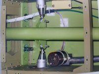
I struggled with the apparently infinite ways to arrange the Ray Allen POS 12 flap sensor linkage and it's attachment to the flap arm. I looked at all the photos and read as many build sagas as I could find.
We finally fixed the sensor to the bulkhead in a position as near as we could get to the "average" position of all the installations we'd seen here. But then, finding the exact place to attach the end of the small linkage from the Ray Allen sensor was equally frustrating. Even with one end fixed, it seemed impossible to find where to put the other end to give a relatively linear travel to the sensor and achieve something nearing full travel of the sensor.
In the end, here's what worked for me:
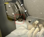
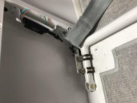
Create the smallish fixture you'll attach to the flap arm from a piece of scrap. While most photos show a single Adel clamp holding it to the arm, I used two to eliminate any temptation to rotate. I also clamped my proto-fitting INSIDE the Adel clamp. Initially, make the proto-fitting overly large. Mine was about 3" long along the flap arm and extended about 2" above the arm. Leave it square.
Make a small length of coat hanger with 90 degree bends at each end. Mine ended up to be 2 1/2 inches long.
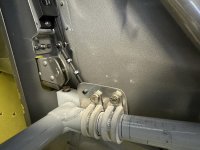
Now fully retract the flap arm, and fully retract the sensor arm. Put one end of the coat hanger in the hole of the flap sensor and swing a radius from that point across the proto-fitting so that it leaves a scratch. Now, fully extend the flaps and fully extend the flap sensor and repeat the radius swing, scratching a second line on the metal. Where those two radius's intersect is where you drill the hole to receive the flap end of the small linkage that connects the two. Trim the excess from the 3"X2" piece of metal.
I used RC control linkage parts to make the small linkage that connects the sensor to the flap arm.
I struggled with the apparently infinite ways to arrange the Ray Allen POS 12 flap sensor linkage and it's attachment to the flap arm. I looked at all the photos and read as many build sagas as I could find.
We finally fixed the sensor to the bulkhead in a position as near as we could get to the "average" position of all the installations we'd seen here. But then, finding the exact place to attach the end of the small linkage from the Ray Allen sensor was equally frustrating. Even with one end fixed, it seemed impossible to find where to put the other end to give a relatively linear travel to the sensor and achieve something nearing full travel of the sensor.
In the end, here's what worked for me:
Create the smallish fixture you'll attach to the flap arm from a piece of scrap. While most photos show a single Adel clamp holding it to the arm, I used two to eliminate any temptation to rotate. I also clamped my proto-fitting INSIDE the Adel clamp. Initially, make the proto-fitting overly large. Mine was about 3" long along the flap arm and extended about 2" above the arm. Leave it square.
Make a small length of coat hanger with 90 degree bends at each end. Mine ended up to be 2 1/2 inches long.
Now fully retract the flap arm, and fully retract the sensor arm. Put one end of the coat hanger in the hole of the flap sensor and swing a radius from that point across the proto-fitting so that it leaves a scratch. Now, fully extend the flaps and fully extend the flap sensor and repeat the radius swing, scratching a second line on the metal. Where those two radius's intersect is where you drill the hole to receive the flap end of the small linkage that connects the two. Trim the excess from the 3"X2" piece of metal.
I used RC control linkage parts to make the small linkage that connects the sensor to the flap arm.
Attachments
Last edited: