What's new
Van's Air Force

Don't miss anything! Register now for full access to the definitive RV support community.

RV-10 Power Block Diagram

charlesmc

Member
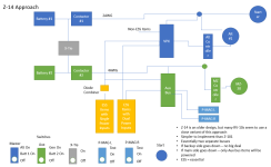
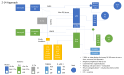
Hi - Looking for critiques of our RV-10 power wiring diagram. I've put together multiple block diagrams including ones based on Z-13, Z-14, and Z-101. However, Bill Judge forwarded me a presentation that he gave that included a "get home" configuration that seemed really interesting. We're keeping it at a block diagram level now and will go into further detail once we get general consensus on the block diagram. We've also been debating a Z-14 approach.

As background, my partner and I are coming from a C-182 club where we lost an alternator approximately every six months. We had alternator failures at night, in IMC (2X), first thing on an engine break-in flight, on a commercial check ride, and my partner was stranded on a long cross-country. So, we are looking to create a very robust system as we fly a fair amount of IFR and we are very sensitive to alternator failures based on prior experience.

Things we have decided on already (we have done our research on these items) - dual ETX batteries, VPX, 60A primary alternator, 30A Monkworkz backup generator, P-MAGs.

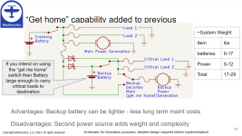
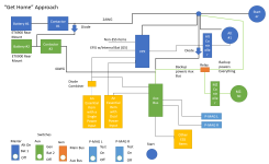
The top image is a slide from the Bill Judge presentation. The bottom is our block diagram that we are hoping to get feedback on. Any mistakes in implementing Bill's circuit are completely my own.
1712538335959.png


1712539367312.png
 
Hi - Looking for critiques of our RV-10 power wiring diagram. I've put together multiple block diagrams including ones based on Z-13, Z-14, and Z-101. However, Bill Judge forwarded me a presentation that he gave that included a "get home" configuration that seemed really interesting. We're keeping it at a block diagram level now and will go into further detail once we get general consensus on the block diagram. We've also been debating a Z-14 approach.

As background, my partner and I are coming from a C-182 club where we lost an alternator approximately every six months. We had alternator failures at night, in IMC (2X), first thing on an engine break-in flight, on a commercial check ride, and my partner was stranded on a long cross-country. So, we are looking to create a very robust system as we fly a fair amount of IFR and we are very sensitive to alternator failures based on prior experience.

Things we have decided on already (we have done our research on these items) - dual ETX batteries, VPX, 60A primary alternator, 30A Monkworkz backup generator, P-MAGs.

The top image is a slide from the Bill Judge presentation. The bottom is our block diagram that we are hoping to get feedback on. Any mistakes in implementing Bill's circuit are completely my own.

View attachment 60145


View attachment 60151
I don't like the diode to Battery 2.

It creates a single point of failure on Battery 2. If it puffs up and starts smoking, you can't remove power without shutting down the whole system. (Discounting here turning off both contactors and hoping the MZ30 runs fine without a battery - I don't know if that works)

My favorite two battery / two alternator plan is to split the devices and build two independent electrical systems. Saves me trying to figure out failure modes between them, and resolves worries I have about overvoltage taking out both sides. Half a modern panel is still a pretty luxurious panel, especially when you don't have to worry about running down a battery so have lots of time to evaluate options. In my case I have either the small screen, AP, IFR navigator or big screen, VFR GPS and NAV/COM. You can diode-or anything you think will spike your workload too much if it goes dark.

If you prefer your layout, it works too. You do have to worry about the backup powers everything being on when the starter gets turned on since it will flow lots of amps through small wires Cleaner may be to just put a relay as a bus tie with 2awg in the back next to the other contactors. Does the same thing electrically, but provides a path for big amps.

edit:
One more thought: you will have to size the diodes to handle the max current you could get from a fully charged battery 1 to an empty battery 2, which is pretty significant.

Derek
 
Last edited:
So more like the Z-14 approach with two pretty much independent busses?

View attachment 60293

P-mags....

The idea of the aux bus and the big diode is automatic load shedding. If you don't have that diode, a failure on the Bus 2 leaves you without the critical aux bus.

From here I think you can go one of two ways:

1. Add back the diode to connect Bus1 to Aux. This will give you back the automatic load shedding if bus one fails, but expose you to overvoltage from 1 to 2. If you do do this two considerations: make sure the diode is able to take the full charge rate of the ETX900, and also add a fuse/cb so that you can isolate the Aux bus if it gets a hard short.

2. Move one of the PMAGs to the bus 1 , and allocate your devices so that you basically have two main busses (I call the Bus 1 / Bus 2), either one of which has enough equipment to get you safely to your goal.

In both cases you can close the bus tie to light up the dark side, but you don't want to create a situation where you quickly have to flip switches to keep yourself comfortable, and you fill those gaps with the diode ors.

With option 2, a failure of either bus to provide power will darken half the panel.
With option 1, a failure of the primary bus will darken half the panel and you won't notice the aux alternator has failed since its not doing anything in normal operations.

The pro of 2 is that an overvoltage on 1 won't transfer to 2, and you don't have to worry about a hard short on 2 affecting 1. (Both of these being admittedly much lower frequency than alternator failures).

For me the dioded aux bus makes a lot of sense for a dual alt / one battery setup, but adding the second battery allows the added isolation of dual independent busses so might as well take advantage of that. The x-tie allows you to take advantage if the fact that both alternators can provide enough amps to power the full setup indefinitely. I'm an option two guy.

Derek
 
The Achilles Heel in most of these designs is the power for the panel comes on the output of the battery(s) master solenoid. This inserts single fault risk that an be easily avoided.

If you add a power feed from each battery using perhaps a #12 wire, add a relay at the battery(s) to control this feed (or a simple switch on the panel if you can tolerate an always hot wire - I can’t) then you eliminate the single point risk of a master relay failure. You also retain a backup mode to keep the panel up if you open the Master Solenoids for “smoke in the cabin”.

I use four simple 30 amp relays to do this, two mounted near each battery. They each provide “normal” and “alternate“ power to one half of the panel, the panel divided into left and right (right EFIS, Left EFIS, Comm #1, Comm #2, etc.).

This process also eliminates “buss tie” complications a most diodes. I use a single dual package schottky diode in my install. This diode gets power from both the right and left batteries to feed the audio panel if one side goes down. Not required if careful planning is done on what comm is used when with the audio panel in the “no power pass through” mode, but it does add convenience.

Carl
 
The Achilles Heel in most of these designs is the power for the panel comes on the output of the battery(s) master solenoid. This inserts single fault risk that an be easily avoided.

If you add a power feed from each battery using perhaps a #12 wire, add a relay at the battery(s) to control this feed (or a simple switch on the panel if you can tolerate an always hot wire - I can’t) then you eliminate the single point risk of a master relay failure. You also retain a backup mode to keep the panel up if you open the Master Solenoids for “smoke in the cabin”.


Carl

I added a second relay at the battery for a back up master. You just use the same main wire that brings power to the front. If I get a relay fail in flight, I can turn the back up on. I can also start and do everything as the main relay. Its a simple item to add for a master relay back up.
 
I added a second relay at the battery for a back up master. You just use the same main wire that brings power to the front. If I get a relay fail in flight, I can turn the back up on. I can also start and do everything as the main relay. Its a simple item to add for a master relay back up.
Using a backup master solenoid but the same wire as the primary master solenoid does not isolate that big fat wire for the “smoke in the cockpit” scenario without taking out power to the panel.

Carl
 
Using a backup master solenoid but the same wire as the primary master solenoid does not isolate that big fat wire for the “smoke in the cockpit” scenario without taking out power to the panel.

Carl
Correct, this is just one back up addition for relay failure.
 
You might consider adding an IBBS (Integrated Back-up Battery System) to provide power to a few critical instruments should you main power system fail. With a 6 AH battery, you can power several key electronic LRUs for at least a half hour or so to get you on the ground in IFR conditions.

I have one, in addition to a single main battery and 2 alternators, and believe I am well prepared for any electrical system failure.

With your 2 P-mags, which are self powered once your engine is running, you should be able to keep flying in the event of an electrical system failure, just like with a set of mags.

There are many different ways to set up your electrical system, one of the "advantages" of experimental aircraft. So after a bit of thought, select the one you like best and proceed. Don't fall into the paralysis by analysis trap.

Cheers
 
Dave makes a very good point. I went dual bus and I like it, but it is arguably more complex than a dual P-mag airplane needs.

Every relay / component is one more thing that can fail, and that you need to figure out how to test and make sure your back up is working at least one a year. (A backup that isn't tested, statistically does little for time beween failures). If you don't know the backup is broken it does nothing for MTBF. Every level of backup also needs to be reviewed for potential side effects that are not always obvious.

I'd be quite happy flying behind a G5 with a battery backup on a one alternator / one battery system. Especially if I have a charged handheld radio with headset adapter with me. (which I still do with dual bus). Single pilot low IFR it would be a draining flight, but still better than the no-gyro approaches we used to have to do... It does mean that an IFR alternator failure means land now. The IBBS is an easy way to make this even more comfortable.

Add a MK30, you are already way ahead of the game with unlimited duration power if the primary fails. (Enough you could even launch with it - and/or continue to your destination).

Add another battery and you remove it as a single point of failure, but the returns start to diminish since they are pretty reliable to begin with and the complexity invariably needs to go up to ensure that 1. you can charge it, and 2. that its reasonably independent from the other battery so they don't both fail at once making the second battery moot.

As a general rule of thumb, if you ever start worrying about concurrent failures you are over thinking it, particularly in a single engine airplane. Once you settle on the design, consider looking at it again with the lens of what can I remove and still not get into trouble if a single wire/component shorts or fails.

The other lens is that at some point, someone else is going to be flying your plane. The easier it is for them to figure out what is going on when something happens, the less likely it is that they will bend the plane.

Now you get to pick :D

Derek
 
Appreciate all the feedback. I will consider the feedback and work up some additional options.

In the P-MAG documentation, they recommend running a dedicated line from the battery that is separate from the starting/main bus because the main bus voltage may sag during start, impacting the P-MAG starting on battery power before converting to self power. That's why I placed them on the Aux bus with the #4 line going to the front.

-Charles
 
In the P-MAG documentation, they recommend running a dedicated line from the battery that is separate from the starting/main bus because the main bus voltage may sag during start, impacting the P-MAG starting on battery power before converting to self power. That's why I placed them on the Aux bus with the #4 line going to the front.
You have a bit of a head start since you are using the ETX so the voltage is naturally starting higher, and it has low internal resistance so the drop at the battery is lower than a lead acid battery, so you may not need it. Since its in the manual we like to deal with it, though. You have a 5% voltage or so you'll lose in the #2 to the front to contend with.

The PMAG doesn't pull much power so you could alternately run a 16awg wire next to the #2 just for the pmag you are feeding off the main bus, that would get you most of the 5% back and meet the installation guidance. The pmag on #2 of course won't need anything.

I'd like to keep at least one of them powered all the time, so you don't have the embarrassing engine stoppage on rollout if they were both on internal power.

Both approaches meet the single failure not being high risk criteria.

Derek
 
So more like the Z-14 approach with two pretty much independent busses?

View attachment 60293
This is extremely helpful. I've been looking for a way to adapt Z-14 to a VPX for my RV-10. A friend has an RV-10 with a Z-14 like bus (electronic ignitions on the battery buses directly), and I've been working from his design drawings, which were done by the original builder and very complete, but the connections to the VPX have slowed me down (I'm a chem E, not an electrical E).
 
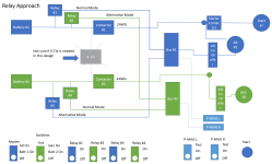
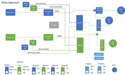
I believe that this is how the relay approach works from my simplistic block diagram perspective.

Normally relay #1 is powering bus #1 and relay #4 is powering bus #2. If the primary alternator goes down, then you can flip relay #3 to ON and apply bus#2's voltage to bus #1 and vice versa. This is also true if a relay goes down, you can just re-route power to the rear deflector shields, I mean other bus.. And you can also have contactors go down and through relay flipping still have power to both busses.

I think Carl said there was a diode somewhere in the design. I'm not sure where. Correction: he is using the diode package to "or" the power to the COM radio.

This relay approach taking power off between the battery and contactor is also used in the Z-101 approach.

I initially thought that the x-tie wouldn't be productive in this approach, but as I'm writing this, I think that it does provide you the ability to put the batteries in parallel for cranking the engine.

1712766363285.png
 
Last edited:
Hi Charles,

Just on the X-Tie position - here and above. Typically it would be after the two contactors. That allows you to isolate the batteries from the bus. With the X-Tie before the contactors you always have to connect both batteries to the bus if you want to x-tie.

I would contend that with two batteries and two contactors and an x-tie behind those two contactors, you can cut any single wire, or fail any one of the contactors and still get power to where you need it. Since I have two contactors connected to two batteries, I'm no longer worried about a contactor failure.

The additional relays and busses adds too much complexity for my taste. They do give you more options to squeeze some more Ah out of the two batteries, but a lot has to go wrong before you need that in a two alternator ship. A number of the scenarios you could bypass with it such as shorts on fat wires, would be too hard to troubleshoot in the air. Its really hard to tell where the electrical smoke smell is coming from / came from in flight.

That said, if it keeps you up a night.....

Derek
 
Thanks Derek. I have adjusted the x-tie connection in both the Z-14 and relay approaches. I also added the P-MAG "mini bus" to the Z-14 approach.

1712768977831.png

1712768994675.png
 
I'm early in the design phase for my RV-10 so this has been very helpful! Thanks!

I want to make sure I'm fully understanding the "Relay Approach" diagram. It seems the relays are there to provide backups in the case of a contactor failure, correct? If that's correct, then:
  • I would think you need either the X-Tie OR the relays, correct? I think they both accomplish the same thing -- keeping both busses "hot" even if one of the contactors was to fail.
  • Assuming you can safely complete your flight with either Bus #1 OR Bus #2 then really you don't need either the X-Tie or the relays. But having one of them offers a certain amount of convenience (so you don't have to complete your flight with some of your electronics dead).
 
Hi Kirk,

For your 1st question, it depends on what is down stream. Bus 1 and 2 may have a subset of important things rather than the full bus and be wired with small'ish wires so you would not, for example, want to hit the starter button using those wires as an x-tie. You would likely wire the switches so that you can't accidentally bus tie them.

For 2. That's what I like about the solution - completely independent and you don't have to hit the switch if you are worried about damage on the dark side. If you go x-tie less you have to be very careful of what is on each side, but you can make it work with what we normally put into IFR airplanes. One scenario I did not think of until it was flying is that if your small backup alternator can't generate enough amps at low RPMs to cover the full load on bus 2 turning the tie on while on the ground makes the warning light go out.
 
My 2c, forget the VPX (brkrs/switches are bulletproof), single bus, single battery, dual alternators (B&C primary with B&C or MKW backup).
Glass panel has it's own TCW BU bat and so does a G5.
KISS is your friend.
 
Last edited:
Back
Top