What's new
Van's Air Force

Don't miss anything! Register now for full access to the definitive RV support community.

Homemade Tool

DanH

Legacy Member
Mentor
I think you can buy one of these, but I often make my own tools. I am a cheap SOB.

A piece of aluminum plate, two 1/4" hardware bolts, a few other bits, and some welding.

IMG_20240113_164551229.jpg


IMG_20240113_164520631.jpg


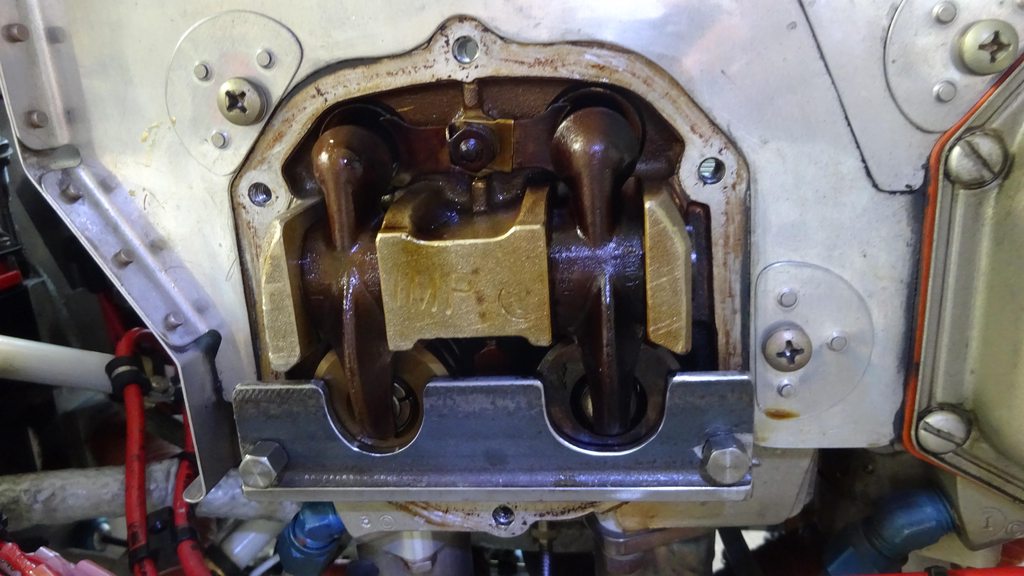
Park the cylinder on TDC, vales closed. Spin the threads into the valve cover screw holes until snug, then one extra turn. Pushes the valve in just a smidge, so no strain on the rocker arm shafts, and they can be pushed out.

IMG_20240113_164627962.jpg
 
seems much more elegant than the clamps I use to bleed down the plungers and a heck of a lot faster.
 
more elegant than the clamps I use to bleed down the plungers
Same here... using the red ones as sold by ACS, but this seems way nicer (y)
I will of course use some of my thick (1/4 or thereabout) scrap aluminum to copy that. Thanks DanH!
 
Same here... using the red ones as sold by ACS, but this seems way nicer (y)
I will of course use some of my thick (1/4 or thereabout) scrap aluminum to copy that. Thanks DanH!
Dan, my friend, you are wayyyyyyy to talented!
Tom
 
Dan, my friend, you are wayyyyyyy to talented!
Tom

Naaa. Can't take credit. An A&P buddy had the basic tool hacked out of scrap steel plate combined with plain bolts and washers. I just borrowed the concept and made it pretty. Made one for him while I was at it.
 
Naaa. Can't take credit. An A&P buddy had the basic tool hacked out of scrap steel plate combined with plain bolts and washers. I just borrowed the concept and made it pretty. Made one for him while I was at it.
Ah! that's nice of you
I get a laugh out of people who look into my tool boxes and say "What is this for?" I have to explain the reason why I made the tool and the few times I needed it.
Love building tools to make the job easier and funner.
My luck varies Fixit
 
Is that for a 360 parallel valve? if so would you share the dimensions?

Next the valve wobble tool?
 
The ability to make tools was an "a ha!" moment for me when one of my old friends showed me some of his purpose-built tools. I'm sure this post will trigger some interesting innovations!
 
The ability to make tools was an "a ha!" moment for me when one of my old friends showed me some of his purpose-built tools. I'm sure this post will trigger some interesting innovations!
It was an “a ha” moment for man, separated us from animals. My wife has a small collection of ancient hand axes, the first tools, used for everything from cleaving meat to showing off your skills in making one to attract a mate, to show you could provide…. Is that what you’re doing Dan!
These tools where not only first, but the only tools man used for hundreds of thousands of years. Dans tool may not last that long but it will certainly outlast us.
Thx for sharing Dan. I have a “valve wizard”, but solution is simple and can be easily made with basic shop tools. Nice.

By the way, if the T bolt seems like it takes a lot of grunt to depress the valve, before you start cranking on the bolt, give the valve spring a sharp whack to loosen the keeper. I had one that was super tight. You don’t want to risk stripping the valve cover hole.
 
Is that for a 360 parallel valve? if so would you share the dimensions?

Next the valve wobble tool?
Dan,
I can supply you with info on building your own Valve Stem Wobble Tool. Not my design [Ion Huss], but very well done. Anyone who wants this info, contact me via Conversation [aka PM]
 
Last edited:
Like Dan, I am a cheap SOB as well. And I love making my own tools. Sometimes I have to stare at something for a while :unsure: before I can visualize the tool that I need to make.

That said, I just crafted one of the...what would this be called....a valve spring unloading tool?... I started with Dan's drawing and redrew it on my drafting board. Then went out to the airplane to confirm dimensions. I found the measurements in the drawing did not quite line up with my O-320 head. I had to tinker with the drawing a bit to determine where things went before I finally set it to the scrap 3/8 inch aluminum pieces (overkill!) I had lying around. Even then, after drawing the pattern on the aluminum, went out and compared what I was about to make with what the cylinder head needed. My final drawing appeared to be correct. It was a mild PITA in that my band saw needed some new parts, so it was all done with the use of my handy-dandy hack saw. Good exercise. And some step drills, Dremel, files . Finished with the Scotchbrite wheel.

SO: put your own drawings to the test. Go out to your engine and MEASURE to make sure everything lines up. Correct your drawing as needed before you start cutting; you don't want to make this twice! Then you will have a pretty cool tool that will be passed down for generations! 😊 That sucker ain't going ANYwhere! 1000 years from now they will dig that up and think.....huh.....must have been a piece of jewelry something from some kind of a cult.......:ROFLMAO::LOL:
 
Nice! Any issue getting go-no-go gauge in there, or do you need to remove it entirely rather than just release tension? Seems like there's plenty of clearance given the Lycoming gauge is angled.

Nice and simple! Looks much nicer than the valve wizard I have.
 
Not sure if you guys know this but the rockers and the fulcrum can be removed relatively easily without tools. This tool cannot push the springs in far enough to remove the keepers.
 
Nice! Any issue getting go-no-go gauge in there, or do you need to remove it entirely rather than just release tension? Seems like there's plenty of clearance given the Lycoming gauge is angled.

Nice and simple! Looks much nicer than the valve wizard I have.
The gauge used on the angle valve engines is angled; the gauge used on parallel valve engines pushes against the valve extension at a 90 degree angle. So: no, this is not good for measuring the wobble. See below.
Not sure if you guys know this but the rockers and the fulcrum can be removed relatively easily without tools. This tool cannot push the springs in far enough to remove the keepers.
No: this tool is just to decrease the tension on the valve springs to let the rocker shaft be more easily removed. Yes, you can do it without this but this tool makes it MUCH easier. Very easy to fabricate; just a minor PITA. This is NOT a wobble test tool. That is a completely different tool. It is NOT a valve spring compression tool for removing the keepers and, ultimately, the springs. That is another tool altogether. Your Valve Wizard or other tool would be the one for that. THEN you bolt on the wobble tool to measure movement of the valve stem. See Lycoming SB 388C. ACS sells that tool for $259 with the dial indicator. OR you can make your own. There are multiple designs out there. Look at the one from ACS; surely you can make that on your own....... I'm in to being tool-independent.... :LOL:
 
Last edited:
Yep, works pretty good, thanks for the idea DanH (y)

Now if I could have those T-handles in the same red... maybe I'll upgrade one day.
Had some 6061-T6 in my "trash" box, and used that to manufacture said plate... I'm happy to report that despite being only 15/64" (6 mm) thick aluminum, it held pretty good and did not bend any when I did my 400H wobble inspection today.

PS
All good, but for cylinder #2 having barely any play, so the valve was dropped into the cylinder, its stem cleaned from the black gum, and some miraculous fishing performed to reinstall the valve. Ah yeah, and also having fun chasing the wandering keepers...


plate.jpg
 
Not sure if you guys know this but the rockers and the fulcrum can be removed relatively easily without tools. This tool cannot push the springs in far enough to remove the keepers.
That I knew, but not being able to remove the keepers was my question.
 
Back
Top