What's new
Van's Air Force

Don't miss anything! Register now for full access to the definitive RV support community.

Displaying Monkworkz current load on G3X

MS19087

Well Known Member
Soon integrating, a monkworkz back up alternator with my G3 X touch. Bill supplies a 0 to 2.7 V output signal which is linearly proportional to current load seen by the alternator. Question is how do I input that to my GEA-24 so I can display load just like my main alternator? Any feedback is appreciated.
 
See Garmin G3X Installation manual, revision AU, Section 30.4.32.15. Wire the MZ30L Shunt Hi/Lo output (Output Molex Pin 3 and 4) to the GEA 24 SHUNT 2 input - Pins 35 & 34. Configure the SHUNT 2 display/type/scale factor accordingly. I also used the MZ30L "Active" output to a spare GP input on the GEA 24 to tell me when/if the MZ30L was active, It will indicate on the CAS display as "Standby ALT" in white.
 
Any update on your installation? Both FWF and G3X pictures would be appreciated.
Uhm - sure -- been working great for better part of a year.

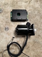
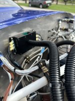
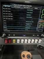
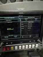
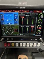
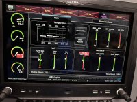
I put the controller/regulator on the firewall directly behind the generator, routed and dressed all the wiring so it wouldn't tangle or create problems. Connected the Shunt output of the MZ30L controller to the GEA24 Shunt 2 input, renamed it STBY AMPS and calibrated it so it matched what I measured with my Fluke on the output side of the controller.

see attached screen grabs.

IMG_4561.jpegIMG_4564.jpegIMG_4568.jpegIMG_5160.jpegIMG_5162.jpegIMG_5161.jpegIMG_5163.jpegIMG_5164.jpeg
 
Uhm - sure -- been working great for better part of a year.

I put the controller/regulator on the firewall directly behind the generator, routed and dressed all the wiring so it wouldn't tangle or create problems. Connected the Shunt output of the MZ30L controller to the GEA24 Shunt 2 input, renamed it STBY AMPS and calibrated it so it matched what I measured with my Fluke on the output side of the controller.

see attached screen grabs.
Brian,
Do you find it the linear voltage provided by MKZ is truly linear and provides an accurate Amp reading as oppose to putting a customer provided shunt?
I have an extra shunt and I am wondering if it is worth using that or just simply stick to what MKZ provides.
 
The MZ30L has two current outputs -- proportional and shunt. I used the shunt hi/lo output wired to the GEA 24 "SHUNT 2" inputs. Calibration was pretty straightforward, once you run the Garmin installation manual through the Garminspeak-to-Human Converter... (Must be Kansas/Oregon thing :) )
 
The MZ30L has two current outputs -- proportional and shunt. I used the shunt hi/lo output wired to the GEA 24 "SHUNT 2" inputs. Calibration was pretty straightforward, once you run the Garmin installation manual through the Garminspeak-to-Human Converter... (Must be Kansas/Oregon thing :) )
I would really like to get a copy of the "Garminspeak-to-Human Converter" even if I need to briefly go to Kansas or Oregon ;)
I will copy try your setup using the shunt which if the old manual that I have still valid it would be pin 3 & 4 of the MZ30. I guess your config that showed .27 for the multiplier threw me off thinking you are using the voltage (pin 5)

Thanks again.
 
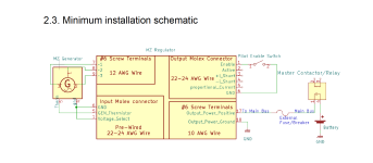
Pinouts for the MZ30L. And exercise caution as the FemtoMolex(TM) and 26ga (ok, 24ga) wire is PITA to work with.

Screenshot 2024-02-07 at 4.09.23 PM.png
 
Seems a bit redundant to run the additional shunt wires from the MW for another amp gauge. Assuming you have the MW output tied to the same post as then main alt (main shunt) then you will have a current reading from the MW if you turn off the main alt or it fails just like normal.
An unnecessary complication with little/no benefit IMO. I look at everything using the KISS principle, making things more complicated just for the fun of it usually results in a less reliable system. The goal should be how do I make things simpler, not more complex.
 
Last edited:
Seems a bit redundant to run the additional shunt wires from the MW for another amp gauge. Assuming you have the MW output tied to the same post as then main alt (main shunt) then you will have a current reading from the MW if you turn off the main alt or it fails just like normal.
An unnecessary complication with little/no benefit IMO. I look at everything using the KISS principle, making things more complicated just for the fun of it usually results in a less reliable system. The goal should be how do I make things simpler, not more complex.

Devil is in the details, of course. I opted for a shorter run of wire to the buss feed-point which, of course, is downsteam of the primary shunt. This necessitated a separate shunt/instrumentation surface.
 
Seems a bit redundant to run the additional shunt wires from the MW for another amp gauge. Assuming you have the MW output tied to the same post as then main alt (main shunt) then you will have a current reading from the MW if you turn off the main alt or it fails just like normal.
An unnecessary complication with little/no benefit IMO. I look at everything using the KISS principle, making things more complicated just for the fun of it usually results in a less reliable system. The goal should be how do I make things simpler, not more complex.
I agree as I am not seeing much benefit as these MZ and Primary Alt are not expected to be active simultaneously. I think just a discrete connection to indicate that the MZ is the active ought to be sufficient.
 
Back
Top