I took delivery of my kit last week and decided to start with finishing both pre-built tanks since I have so many back ordered parts. The left side went fine, but when I inserted the fuel sender into the right tank, the screw holes didn’t line up. I contacted builder support and was told their documentation shows we should have two different fuel senders, IE F-385B for the left side, and -385C for the right. I let them know that both the KAI (revision 0) and my inventory list show two of the-385Bs and they asked me to return one for exchange. I tried to put a note in the wiki, but it wouldn’t post.

Van's Air Force
You are using an out of date browser. It may not display this or other websites correctly.
You should upgrade or use an alternative browser.
You should upgrade or use an alternative browser.
Check your fuel senders
- Thread starter Poimutt
- Start date

So I checked mine today, two -B’s so I sent an inquiry to kits@vans. Reply this afternoon:
Contrary to the part number and description, two rights will be used as they can be engineered to be used on either side. Section 21 calls out on page 2 for IE F-385B x2, one for the left, one for the right!

Contrary to the part number and description, two rights will be used as they can be engineered to be used on either side. Section 21 calls out on page 2 for IE F-385B x2, one for the left, one for the right!
Has this been resolved? No one seems to know the right answer. I ask vans a while ago with no response and just sent a new email yesterday. As far as I can tell we need a left and a right and many are saying they were told you need 2- F-385B's. The B only works on the left tank.
The only way to use the B's on both is you have to install it upside down on the right tank and it sounds like the sender will not work if upside down even you bend the wire to work?
Hopefully someone knows how we should be proceeding.
The only way to use the B's on both is you have to install it upside down on the right tank and it sounds like the sender will not work if upside down even you bend the wire to work?
Hopefully someone knows how we should be proceeding.

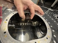
I don’t know the answer to whether it is right (correct) or not, but if the float in your picture is on the bottom of the tank it does look like the electrical wire will restrict the float arm from fully extending up as the tank fills with fuel.This is what it looks like, needs to be upside down to fit. Anyone know if that is right?
I could be wrong, but I think all of the popular EFIS systems that provide for fuel level indication utilizing resistive fuel senders, expect the standard 30 ohms when full and 240 ohms when empty resistance values.
For this to occur with the senders that are supplied by Vans, the angle bracket that the resistor is mounted to needs to angle/point towards the bottom of the tank.
If it doesn’t, then the 30–240 ohm orientation will be flipped around so that the resistance will be 30 ohms at empty and 240 ohms at full.
After thought- Since the calibration process develops a look up table of voltages for full versus empty, maybe it doesn’t matter, and it can be made to work with the resistance, sweeping either way.
After thought follow-up
I asked Rob at AFS if their system would properly calibrate if the resistance sweep was reversed from the traditional norm, and he said “it should”, so it seems it would be fine with a Dynon / AFS system at least.
If someone for some reason chose to use legacy analog guages one tank will indicate backwards.
Last edited:
Hey Scott - I can confirm what you hypothesize in your musings and what Rob said - I have Dynon, GRT and Garmin in our Avgas airplanes, and they al calibrate fine no matter if the resistance goes up or down as the tank empties (or fills). The calibration curve gets built and the systems can deal with reversed senders.I could be wrong, but I think all of the popular EFIS systems that provide for fuel level indication utilizing resistive fuel senders, expect the standard 30 ohms when full and 240 ohms when empty resistance values.
For this to occur with the senders that are supplied by Vans, the angle bracket that the resistor is mounted to needs to angle/point towards the bottom of the tank.
If it doesn’t, then the 30–240 ohm orientation will be flipped around so that the resistance will be 30 ohms at empty and 240 ohms at full.
After thought- Since the calibration process develops a look up table of voltages for full versus empty, maybe it doesn’t matter, and it can be made to work with the resistance, sweeping either way.
After thought follow-up
I asked Rob at AFS if their system would properly calibrate if the resistance sweep was reversed from the traditional norm, and he said “it should”, so it seems it would be fine with a Dynon / AFS system at least.
If someone for some reason chose to use legacy analog guages one tank will indicate backwards.
This is good news if the sender will work both ways. The other issue I saw was the float hits the nut plate so I plan to bend the rod opposite to get the float away from the nut plate. (It will end up under inspection cover) Hopefully Vans responds to my email to tell us what the intent is for the sender.
Attachments
It will not work! according to the factory you need to install the "B" sender upside down to match the hole pattern. This does not work for the required clearance top and bottom as per plans. The sender itself is angled so that it will not have the same geometry the pivot point for rotation of the arm, is not the same. I tried several times to overcome it does not Work! I have yet to receive a solution other then put it in and reverse the resistance reading on your avionics. very poor solution to Vans mess up.So I checked mine today, two -B’s so I sent an inquiry to kits@vans. Reply this afternoon:
Contrary to the part number and description, two rights will be used as they can be engineered to be used on either side. Section 21 calls out on page 2 for IE F-385B x2, one for the left, one for the right!
They have the correct senders in stock both the "B" and "C"s but want to sell you a new one for over $80, if you order it from the factory directly its around $40.
Is anyone else experiencing this problem?
My kit initially came with a B and C, then they sent me another B so I have 3 senders.They have the correct senders in stock both the "B" and "C"s but want to sell you a new one for over $80, if you order it from the factory directly its around $40.
Is anyone else experiencing this problem?
I have not installed them yet, have been watching to see what others come up with.
Before folks assume that a specific sender can be installed in an arbitrary orientation, I vaguely remember discovering that the SW senders do not have evenly spaced screw holes - they are effectively “keyed” so that they can only go in one way. I think I remember that from 20 years ago however, so just something to check before throwing money away on a different sender….
