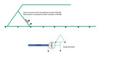
I've never really understood how (or why) the Archer antenna worked. I attached a simple block diagram + schematic of what I recall the thing looked like from a block-ish diagram and an electrical schematic.
I "think" the magic happens due to the 60° angled legs (creates the aperture to the wave front) and the size (capacitance) of the capacitor formed by the stub and the fiberglass spacer.
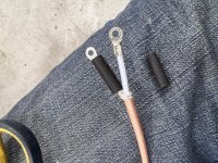
I've seen (and built) other gamma match antennas, etc. but I do not recall seeing one where the matching network is open with respect to the reflector/radiator like it is on the Archer.
Bob, Carl, you guys understand the physics a whole bunch better than I, can you shed some light on what's happening here?
Bob provided a nice response. I’ll add a couple of thoughts:
- The 60 degree triangle has nothing to do with the antenna itself, it just provides a way to feed the antenna.
- As with all quarter wave antennas, the base is the high current point, the tip is the high voltage point (current and voltage are 90 degrees out). So the base impedance is ~0 ohms and the tip impedance is infinite. Keep in mind this is RF impedance at the operating frequency, not DC resistance. RF and DC are very different animals.
- Now that we know the antenna impeadance is zero at the base and infident at the tip, someplace between the base and tip will the impedance will be 50 ohms. This is the point we want to feed the antenna with our 50 ohm coax. This is the point where the “triangle arm” connects to the antenna. We use a gamma match network to allow the addition of a capacitor to balance out the inductance of the arm that connects to the antenna.
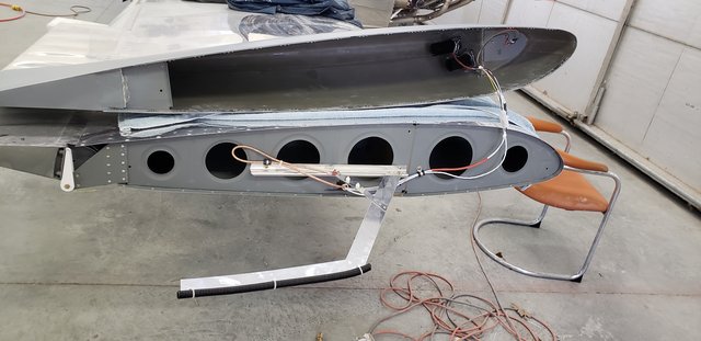
Some thoughts on how to mount these antennas:
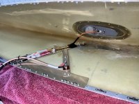
- I would never run NAV/Strobe or landing light wires alone the antenna as shown in the Archer instruction. You are asking for trouble. Just don’t do it.
- I suggest that mounting it further aft and to the end rib solves this light wire issue, as well as everyone’s obsession to achieve a perfect DC ground (in my opinion misplaced as the antenna wants an RF ground, not DC - but that is a much longer discussion).
- The attached photo is how I mount my wingtip antenna. I make the antennas to stick out further into the wing tip. The most expensive part of this antenna is the hardware. I have VOR ranges well beyond 100nm on these antennas, and ILS way beyond practical ranges.
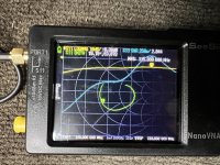
Note, do not attempt to make this antenna unless you have access to an antenna analyzer. To make these antennas sing, you need to tune them (as in length and adjusting the gamma match capacitor). I strongly suggest verifying all antennas with a real analyzer - so a great shared tool for you local EAA chapters.
Carl