I have an internal regulated Denso on my plane it's been in it since 2015 still working fine and when I turn that switch off that you're saying is not the field it definitely turns the alternator off . This is the one that I have and you turn the switch off that controls that little wire coming out of the back and that alternator shuts down. How do you have it wired so that it doesn't turn the alternator off mine is Wired from power directly from the battery bus and I turn that switch off and the alternator shuts down.
I've read that post that you linked to and that makes no sense to me shuts the master off and the voltage goes to 119 volts that's nuts, something's wrong he didn't have something wired right or had some other malfunction that sounds like full Fielding somehow the only only way to go that high voltage
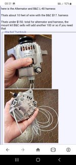
When I get back home I'll fly it take a video of it shutting the switch off in flight and show you the voltage going back to battery voltage. Here's a link to my alternator it's a very simple 40 amp internally regulated Denso
https://www.ase-supply.com/product_p/nd-021080-0760.htm
Ok reread your post, and see you said disconnecting the battery from the B lead is what caused the 119 volts... still sounds strange . The way mine is wired up is through a double pole double throw toggle I can throw one way and it just disconnects that field wire or the wire you're saying it's not the field wire the 12 volt starting power for the alternator and if I throw the toggle the other way it takes the battery out of the system I'll try it both ways and see what happens I know I've shut the field wire off and that just takes the alternator out of the system and leaves everything else powered up by the battery
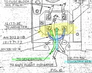
Edit one more time thinking about my system again that double pole double throw toggle when I take it from the alternator throw it goes to off and that disconnects the battery from the system, and then I can throw it the other way to battery only, so I've already disconnected the battery and goes right back to 12 volts whatever the battery is at. My B lead is wired directly to the back of the ammeter from there it's wired to that toggle switch the double pole double throw toggle switch that's where I break the connection to the battery I never got no increase of 120 volts whatever that guy did he had something funky going on