

Van's Air Force

The definitive Van's Aircraft support community! Buying, building or flying an RV? Join our exclusive family of mentors and enthusiasts!

G3X to Axis upgrade - power questions

Ben Ellis

Well Known Member
Sponsor
This question is more for G3XPERT but I'm putting it out there for everyone. I'm going to be upgrading my GDU460 to a GDU116Bx as soon as I receive the unit from Stein. So I have started to plan the changes to my electrical system. A few issues that have come up:

The installation manual says that if you used the GAD 27 keep alive function with G3X that you should disconnect this and connect the Axis flight display directly to the electrical system. Without the GAD 27 or a backup battery, does the Axis display have some sort of brownout protection that will keep the Axis display powered when cranking the engine? If not, does Garmin recommend a backup battery?
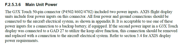
1783898866888.png

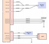
Also regarding the increase from 2 power inputs to 4 power inputs for the J1012 connector -- which note 6 to Figure B-1.1 says is for the PFD/MFD/GPS functions -- I have several questions:

1) Is the J1012 connector also for the USB-C charging (since I note the power inputs on the J1015 connector are only needed for the GDU116C/NC units per note 8 to Figure B-1.1)?
2) The paragraph above says that if you have a backup battery, you can put it into one of the J1012 power inputs. Does that mean that any one of these inputs can power all PFD/MFD/GPS functions, or is there reduced functionality if only running on one input through the backup battery in the event of electrical system failure? Assuming the answer is all these functions can be powered on one input, then what's the purpose of 4 vs 2 power inputs since 1 extra input would solve for redundancy?
3) Is the GPS functionality referred to in note 6 the built in IFR GPS that comes with the C/NC units or the built in VFR GPS that comes with the Bx unit? If IFR GPS, then are all four inputs still needed for the B units?
4) If all four are truly needed, do they all equally draw the same amount of current? The main reason I ask is because my existing GDU460 wiring is two 22AWG runs, one on a 5A breaker and one on a 5A fuse (fed from the e-bus to which the GAD27 keep alive power flows). Ideally I could keep those two runs and just add two more that are 20AWG.
5) What does Garmin recommend for the breaker size that all four inputs are tied to?
6) Usually when I see splicing like that it is a bigger wire run that is stepped down in gauge to fit the dsub pins. Does Garmin recommend a larger gauge between the breakers and the pin splice?

J1012 Connector:

1783904367136.png

I note the increase in max draw over the G3X's 2A at 14V:
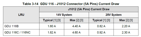
1783905870756.png
 
Last edited:
Installation manual 3.4.2 GDU Power Requirements says "The main 50-pin connector (J1012) has four main power inputs. This connector is present on all display variants. All four power and ground connections should be connected to the aircraft electrical system. It is acceptable to use one of these power inputs for a connection to a backup battery, if equipped."

If one pin connected to a backup battery is sufficient to keep the display working then why are 4 pins needed for normal operation? Wouldn't one expect half the pins to be allocated to primary power and half allocated to backup power?

When Garmin LRU have redundant power inputs then they are often described as "diode ORed". I found no such description of the AXIS DU power input pins.

I would like to see at least a block diagram level representation of the internal power distribution.
 
Without the GAD 27 or a backup battery, does the Axis display have some sort of brownout protection that will keep the Axis display powered when cranking the engine? If not, does Garmin recommend a backup battery?
GAD27 protects against voltage sag while starting. This was important for GDU 4XX, AXIS is capable of handling the temporary interruption however.

A backup battery serves as backup power for the system to operate on, in the absence of the primary electrical system, and is also used to protect against voltage sag during engine start in many G3X Touch systems. We expect many AXIS system to incorporate backup batteries to run the system in the case of an electrical system failure. The use of backup batteries is discussed in the installation manual.

1) Is the J1012 connector also for the USB-C charging (since I note the power inputs on the J1015 connector are only needed for the GDU116C/NC units per note 8 to Figure B-1.1)?
You are correct.

2) The paragraph above says that if you have a backup battery, you can put it into one of the J1012 power inputs. Does that mean that any one of these inputs can power all PFD/MFD/GPS functions, or is there reduced functionality if only running on one input through the backup battery in the event of electrical system failure? Assuming the answer is all these functions can be powered on one input, then what's the purpose of 4 vs 2 power inputs since 1 extra input would solve for redundancy?
Full 27W USB-C charging is not available on only 1 power input pin, which changes the power consumption of the device. The system has different power requirements from G3X Touch in general and we strongly suggest providing power to all 4 inputs. As mentioned in the manual, if a backup battery is incorporated in the system, use one (and only one) of those inputs for that connection.

3) Is the GPS functionality referred to in note 6 the built in IFR GPS that comes with the C/NC units or the built in VFR GPS that comes with the Bx unit? If IFR GPS, then are all four inputs still needed for the B units?
Yes, both. Yes, use all 4 inputs to balance the power load on either variant.

4) If all four are truly needed, do they all equally draw the same amount of current?
Yes
5) What does Garmin recommend for the breaker size that all four inputs are tied to?
If wired as shown, 7.5A @14V.
 
@g3xpert :
Does the 8" portrait display capable of split screen and more specifically, can it display/control the Autopilot much in the same that the G3X has done? Will there be any manual available for the 8"
 
5) What does Garmin recommend for the breaker size that all four inputs are tied to?
6) Usually when I see splicing like that it is a bigger wire run that is stepped down in gauge to fit the dsub pins. Does Garmin recommend a larger gauge between the breakers and the pin splice?
Here's what I'm going with:

1784079511358.png
 
Last edited:
Installation manual 3.4.2 GDU Power Requirements says "The main 50-pin connector (J1012) has four main power inputs. This connector is present on all display variants. All four power and ground connections should be connected to the aircraft electrical system. It is acceptable to use one of these power inputs for a connection to a backup battery, if equipped."

If one pin connected to a backup battery is sufficient to keep the display working then why are 4 pins needed for normal operation? Wouldn't one expect half the pins to be allocated to primary power and half allocated to backup power?

When Garmin LRU have redundant power inputs then they are often described as "diode ORed". I found no such description of the AXIS DU power input pins.

I would like to see at least a block diagram level representation of the internal power distribution.
The 4 power inputs on J1012 are diode ORed. We will clarify this in the installation manual.

@g3xpert :
Does the 8" portrait display capable of split screen and more specifically, can it display/control the Autopilot much in the same that the G3X has done? Will there be any manual available for the 8"
Yes to all questions. The installation documentation will be available closer to the Q1 2027 release date for the 8 inch displays. If there is something you are hoping to work out specifically for your installation as it relates to the 8 inch displays, please email us at [email protected] and we will work to get you the information you need.
 
GAD27 protects against voltage sag while starting. This was important for GDU 4XX, AXIS is capable of handling the temporary interruption however.

A backup battery serves as backup power for the system to operate on, in the absence of the primary electrical system, and is also used to protect against voltage sag during engine start in many G3X Touch systems. We expect many AXIS system to incorporate backup batteries to run the system in the case of an electrical system failure. The use of backup batteries is discussed in the installation manual.


You are correct.


Full 27W USB-C charging is not available on only 1 power input pin, which changes the power consumption of the device. The system has different power requirements from G3X Touch in general and we strongly suggest providing power to all 4 inputs. As mentioned in the manual, if a backup battery is incorporated in the system, use one (and only one) of those inputs for that connection.


Yes, both. Yes, use all 4 inputs to balance the power load on either variant.


Yes

If wired as shown, 7.5A @14V.
So, in addition to power inputs ALL 4 power grounds MUST BE connected ?

Thanks


Tom
 
So, in addition to power inputs ALL 4 power grounds MUST BE connected ?
I'm curious about this too and alternatively, if using all four ground pins, does each wire need to go back to the common ground point or can the four grounds be spliced close to the device with one wire going back to the ground point?

I'm very curious why the device calls for four 20awg power inputs fed from a common breaker and four 20awg grounds to power a max of 4.4A. Is this to lower voltage drop? Or is this one of those things the FAA requires for certification just because? Maybe some of the electrical engineers here can shine some light on this.
 
Back
Top