The Garmin installation manuals contain lots of interconnect drawings but, as every system is a little different, they can't provide a complete diagram for every system. So, how do you know where to stop adding redundant and backup interconnections?
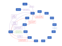
The attached image shows a possible system for discussion purposes.
As an example, take the MapMX link between the GNX 375 and the G5. The Garmin manual says that will allow you to shoot a fully coupled approach if the PFD dies. That's impressive, and probably the best option if you don't have an MFD. On the other hand, if there is an MFD, I'd rather use that because the approach will be the same as normal. Would it be better to send that MapMX link to the MFD instead of the G5?
It's not really a question about this specific case. It's more a question about where to find the information to make an informed decision. Can anyone help me?
The attached image shows a possible system for discussion purposes.
- Green depicts ARINC connections
- Blue is for CAN bus
- Purple is the RS-232 connections that seem (to me) to be essential; and
- Red shows RS-232 connections that seem to be optional.
As an example, take the MapMX link between the GNX 375 and the G5. The Garmin manual says that will allow you to shoot a fully coupled approach if the PFD dies. That's impressive, and probably the best option if you don't have an MFD. On the other hand, if there is an MFD, I'd rather use that because the approach will be the same as normal. Would it be better to send that MapMX link to the MFD instead of the G5?
It's not really a question about this specific case. It's more a question about where to find the information to make an informed decision. Can anyone help me?