What's new
Van's Air Force

Don't miss anything! Register now for full access to the definitive RV support community.

Tail light replacement

mbuto

Member
Hello!
I'm in the process of upgrading all external lights on my RV9-A to LED. My current tail light is a TP20X connected as shown. I need to connect the wire for the position light and ground and leave the Sync and ACL wires alone. I don't think the polarity is marked on the bulb so just trial and error to determine the ground wire? I think I can just solder the connections since I don't have any slack to use any type of physical connector. I'm assuming heat shrink tubing and/or electrical tape will suffice?

Thanks!
Mike
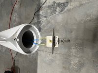
tail-bulb.jpg
 
I’m pretty sure the LED you install is specific to which wire is + or -.. I would use an ohm meter or voltage meter to figure it out before committing to the connection. I would also consider a plug in case someone down the line needs to remove the rudder.. you can just use moles pins and shrink tube.. that’s about as light as anything else!
 
tail light replacement

Turn on the existing position lights and measure (with a multi meter) which of the two wires coming into the tail light measures 12 volts relative to air-frame ground. One wire will measure 12 volts, the other 0 volts.

And, just to be complete, measure the resistance to ground of the "0 volt" wire. it should read 0 ohms (or very close to 0).

The 12V wire is power in to the tail light. The 0V / 0 ohm wire in to the tail light is the ground wire.
 
Last edited:
As Tom mentioned above, use a VOM (Volt Ohm Meter)

Switch the light on to insure you have voltage to the light.
With the switch on, remove the wires from the light, have the VOM in the DC range, ground the Black lead to the airframe and touch the Red lead to one of the wires, one of the wires will show 12 volts and the other will show zero volts, the ground wire.

Looks like Steve types faster
 
You can just do a continuity test with the volt ohm meter.
The one that tones to ground will be the ground (-) side.
The other will be the voltage side (+).
Don't even need to turn on the power.
 
Most aircraft wiring uses crimp connectors instead of soldering, as the latter is more prone to failure due to vibration and fatigue failure. If you do solder make sure the connection is well supported mechanically (shrink tubing, properly applied, helps).
Q: since it appears you are considering flight at night? Many installation install a combination nav light/strobe at that location.

Yes, I have since figured out that crip/spade connectors will be the way to go.

Personally, I don't fly at night, but a) want to be seen and b) want the plane as capable as possible for the next owner.
 
Personally, I don't fly at night, but a) want to be seen and b) want the plane as capable as possible for the next owner.

For day use a strobe (conventional or LED) helps you to be seen, while a nav light is borderline useless. And as far as ‘capable’ is concerned, for night use you likely need both a nav and a strobe. I personally like the combination nav-strobe from FlyLeds.
 
Back
Top