-POSTING RULES

-Advertise in here!
-
Today's Posts
|
Insert Pics
Keep VAF
Going
Donate methods

Point your
camera app here
to donate fast.
|

01-19-2022, 09:41 PM
|
|
|
Join Date: Aug 2017
Location: Melbourne, Australia
Posts: 430
|
|
GMU11 in Left Wing ADAHRS Mount Location
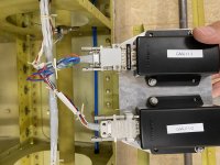
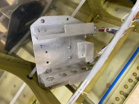
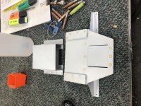
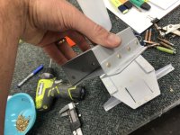
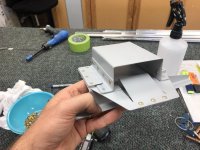
Just running wires before i do the bottom skins, and i was wondering if anyone had any pictures of the GMU11 installed in the left wing ADAHRS mount?
Having trouble visualising how it would be installed so i can still get to the connector (placing the connector forward for ease of maintenance may interfere with the aileron pushrod).
Thanks in advance.
|

01-20-2022, 04:02 AM
|
 |
|
|
Join Date: Sep 2019
Location: Windsor, Ontario
Posts: 523
|
|
Not answering your question however I put mine in the right wing tip as many others have with good results. I did not mount it in the GMU-22 bracket that Van's supplies.
__________________
Glenn Martin
Windsor, Ontario
1941 Tiger Moth
2017 Waco YMF-5
RV-14 Kit # 140694 - First Flight June 22, 2021
RV-14 A - Kit Ordered February 8, 2022
2022 Dues Paid
|

01-20-2022, 03:01 PM
|
|
|
Join Date: Jan 2016
Location: Sugar Land, TX
Posts: 529
|
|
GMU 11 In Wing of RV-10
Since I believe the RV-10 has a similar wing to the RV-14, I think my mounting method may be a possibility.
I had purchased a mounting bracket for the GMU 22 from Stein, before learning that Garmin had released the GMU 11 as part of their G3X system. So I used that bracket to mount my GMU 11 in the right wing, since it made the mounting very solid and easily accessible for future service. I mounted it just inside the outermost rib of the wing. See the photo below. [The blue cylinder behind the GMU is a battery operated light]
I mounted the GMU in the right wing, so as to keep it away from the higher current wires that I ran down the left side of my fuselage. I tried to segregate my wiring between the high current, typically non-shielded wires which I ran down the left side, and the low current, digital, typically shielding wires which I ran down the right side, to reduce the potential for RFI/EMI introduction into the digital systems.
Because I mounted the GMU 11 in the right wing, I also mounted the aileron trim and the autopilot roll servos in the right wing. Since with the Garmin system the GSA 28 roll servo is connected to the trim servo, I didn't want to have to run those wires between the 2 wings. This also allowed me to run the CAN Buss out to the GMU 11 and then back to the GSA28 which has a built in CAN Buss terminator.
Hope this helps.
__________________
Dave Macdonald
RV-10 First Flight April 1, 2020.  Phase 1 Complete
2022 VAF Dues Paid (plus a little more as the site is worth it.)
Last edited by DRMA : 01-20-2022 at 03:16 PM.
|

01-20-2022, 03:16 PM
|
 |
|
|
Join Date: Apr 2016
Location: Melbourne, Australia
Posts: 257
|
|
G'day Trent
Just a quick note to say that if you mount it where Glenn did in post #2 it puts it very close to your lighting when the wingtip is bolted on.
I have had one customer solve interference issues by moving his GMU11 further back on the wing.
Garmin suggests keeping a GMU 1m/3ft away from just about any other electrical device...

__________________
Paul McVitty
Flyleds.com
VAF advertiser
(paid more than asked for this year as well!)
|

01-21-2022, 04:20 PM
|
|
|
Join Date: Aug 2017
Location: Melbourne, Australia
Posts: 430
|
|
Thanks Paul,
I agree - which is why I thought the left wing ADAHRS mount location was a goodun.
In my left wing I will have (I think!) your original position kit and your 4 globe taxi/landing kit. They are all obviously outboard. Then other than that I will have the magnetometer and the oat probe. Oh, also an archer nav antenna in the wing tip.
So running past the magnetometer (within about 10”) will be a twisted 3 x 18awg for taxi, landing, ground, and a shielded 4 x 20 for the position lights. They will run past the magnetometer but think I should be ok with this? There shouldn’t be any major magnetic fields I wouldn’t think?
Right wing has the same lighting, along with a heated pitot, roll servo and trim servo.
|

01-21-2022, 07:55 PM
|
 |
|
|
Join Date: Apr 2016
Location: Melbourne, Australia
Posts: 257
|
|
Well the Garmin manual suggests unshielded wires need to be kept 10 feet/3 metres away... but yes that shouldn't be an issue.
(I think Garmin would prefer the GMU to be mounted with duct tape on a wooden broom handle out in the breeze somewhere...)
I can count on one finger the amount of interference issues Flyleds lights have caused, and it was solved by moving the GMU away more than the 3" it was from the light and wiring.
A wire carrying current generates a magnetic field around it, which is how a motor works as an example.
If the positive wire out to your nearby device creates a 'north' magnetic field around it, then the current flowing in the return wire has a 'south' magnetic field. By twisting the wires together or at least using the same path, the two fields cancel out and the magnetometer sees no net change to the nearby magnetic field.
If you have a GMUxx in a wingtip ensure that everything else in that wing is grounded at the wing root or elsewhere, rather than at the wingtip, otherwise the wing itself becomes that return wire and creates that stray or extra 'south' field that the GMU might get distracted by.

__________________
Paul McVitty
Flyleds.com
VAF advertiser
(paid more than asked for this year as well!)
|

01-22-2022, 08:19 AM
|
|
|
Join Date: Oct 2016
Location: Riehen, Switzerland
Posts: 5
|
|
GMU11 in original Position
This is how I wired mine. To prevent problems with the lighting, I used shielded cables to avoid interference. No issues in the workshop, but I did not fly yet.
|

01-26-2022, 08:05 AM
|
|
|
Join Date: Aug 2020
Location: Ontario, Canada
Posts: 73
|
|
I've been thinking about using the 4 nutplates in the last wing bay towards the tip to mount the magnetometer. I think this may have been intended for a voltage regulator for halogen landing lights. Has anyone done this? Three possible concerns are:
1. Increased CANBUS length
2. Proximity to wing tip strobes
3. Shielding from leading edge.
__________________
RV-14A
Empennage - 95% complete
SB Wings - 80% complete
SB Fuselage - ordered Aug '21
Finishing Kit - ordered Jan '22
2022 Dues paid
|

01-30-2022, 04:22 AM
|
|
|
Join Date: Aug 2017
Location: Melbourne, Australia
Posts: 430
|
|
Quote:
Originally Posted by pentoli
This is how I wired mine.
|
Just out of interest (hard to see from your photo) did the brackets leave the mounting plate for the unit parallel to the permanent plate installed in the wing?
|

02-07-2022, 09:57 AM
|
|
|
Join Date: Oct 2016
Location: Riehen, Switzerland
Posts: 5
|
|
Yes, we used the rail from the plans and produced a plate that slides in.
|
Thread Tools |
Search this Thread |
|
|
Display Modes |
Linear Mode
|
Posting Rules
|
You may not post new threads
You may not post replies
You may not post attachments
You may not edit your posts
HTML code is Off
|
|
|
All times are GMT -6. The time now is 05:00 PM.
|