

Has anyone built an archer antenna themselves? Shipping from the states is terrible at the moment.
Some specific questions:
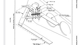
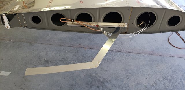
1. Does the thickness of the sheet matter? I was thinking of mounting it on an angle riveted to the wingtip, and 0.025” seems pretty light weight and fragile (when the wingtip comes off).
2. I assume anything non conductive can be used an the insulator? (Like fibreglass or thin nylon etc?)
3. If I wanted it to be wider (wingspan wise) to reach to the outside of the wingtip fibreglass tip (this is on a -14) is it just a matter of scaling up all of the dimensions? (Including the size of the triangle and width of the strips?). Or does the triangle need to remain the same size and I can just extend the spanwise arm?
4. Am I correct that the shield of the coax needs to connect using brass hardware so it is grounded to the part attached to the wing rib? And the centre of the coax needs to connect to the small strip which is not electrically connected to anything?
Sorry if these are basic questions - all I really have to go on is the image on page 13-16.
Unfortunately I don’t have a lot of clues about antennae - I’ve read the aero electric connection but I’m more confused than enlightened.
Some specific questions:
1. Does the thickness of the sheet matter? I was thinking of mounting it on an angle riveted to the wingtip, and 0.025” seems pretty light weight and fragile (when the wingtip comes off).
2. I assume anything non conductive can be used an the insulator? (Like fibreglass or thin nylon etc?)
3. If I wanted it to be wider (wingspan wise) to reach to the outside of the wingtip fibreglass tip (this is on a -14) is it just a matter of scaling up all of the dimensions? (Including the size of the triangle and width of the strips?). Or does the triangle need to remain the same size and I can just extend the spanwise arm?
4. Am I correct that the shield of the coax needs to connect using brass hardware so it is grounded to the part attached to the wing rib? And the centre of the coax needs to connect to the small strip which is not electrically connected to anything?
Sorry if these are basic questions - all I really have to go on is the image on page 13-16.
Unfortunately I don’t have a lot of clues about antennae - I’ve read the aero electric connection but I’m more confused than enlightened.
")

