RFSchaller
Well Known Member
Maybe, Jim —- or maybe he REALLY made some mods!


Oops, sorry I never look here.Hi,
can you give me some information how you did it? Especially considering the wiring? I own a RV-12 ULS (still with the D180) and I am also thinking about adding the trim and AP disconnect to the yoke. However, Vans couldn't help me with it and now I am not sure how to approach the change. Do you have a wiring scheme you are willing to share?
Thanks!
Walt
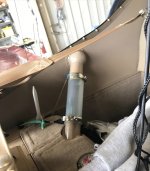
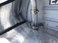
Where did you get the clear tubing? Locally or did you order it?
Thanks
In the April 2022 issue of EAA's Sport Aviation magazine, Vic Syracuse, in his article "Impediments to Selling," states "The only way you can make modifications are with authorization from the manufacturer." He goes on to say that doing so "invalidates the airworthiness certificate." I recently purchased an RV-12 from the builder and I am totally confused.
In the April 2022 issue of EAA's Sport Aviation magazine, Vic Syracuse, in his article "Impediments to Selling," states "The only way you can make modifications are with authorization from the manufacturer." He goes on to say that doing so "invalidates the airworthiness certificate." I recently purchased an RV-12 from the builder and I am totally confused.
Yup, I immediately reversed the flap switch. I had to call Van’s to confirm the plans were correct. Was told it’s to operate in the direction of a manual flap handle. Since +90% of my flying had been with electric flaps, reversing was a safer option for me. And a friend of mine did add a flap switch to their iS panel.
I left the console switch in place but it is no longer connected.
For what it's worth.... if you leave a switch in place and it is inoperable... you should mark it as such... "IN OP"
Has anyone moved their flap switch from the center console to the panel? And/or, has anyone reversed the switch so that switch up is flaps up, and switch down is flaps down? The position and orientation of the switch drives me crazy!
Has anyone moved their flap switch from the center console to the panel? And/or, has anyone reversed the switch so that switch up is flaps up, and switch down is flaps down? The position and orientation of the switch drives me crazy!
Anyone got anything better than the typical "bolt a 4x4 to the pedal" option. Looking for a way to "move/rotate) the pedals closer to the short pilots (both sides) feet.
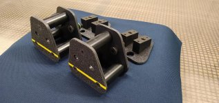
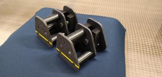
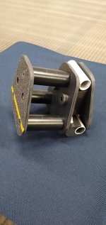
Updated Pictures!!! Did a fit check yesterday on a flying RV12 ULS and it worked like a champ. 3" standoff on the ones you see. Will go fly with them tomorrow and report back. Will also get photos mounted on the plane. They were rock solid on the fit check!!!
What was the source for those extensions?
I made them here at my shop. It's what happens when you have a CNC machine shop.... a wee bit overkill but I wanted something robust that didn't feel like a hack and wack. Two bolts (per pedal) and you're flying. No modification to the plane needed.
Thinking of making a base plate that fits on the stock pedals to give you a more robust feel.
The reason I ask is that a lot of us have CNC equipment. I wasn't sure if this was a design that's been mentioned earlier in the thread or elsewhere, or something new you are trying.
Do you intend to make this a product? If not, share more about the design and dimensions since it's working? I might be interested either way. I have the equipment to do it, but also have plenty other things to work on.
Updated Pictures!!! Did a fit check yesterday on a flying RV12 ULS and it worked like a champ. 3" standoff on the ones you see. Will go fly with them tomorrow and report back. Will also get photos mounted on the plane. They were rock solid on the fit check!!!
Do you have your upgrade process detailed anywhere online?
I do not.Do you have your upgrade process detailed anywhere online?
I do not.
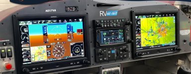
The GPS175 is connected to the system via RS-232 to the GDU and ARINC 429 to the GAD 29. The GPS20A was removed (and I guess I should get it listed in Classifieds) but the GA36 WAAS antenna the GPS20A was using is compatible with the GPS175 so it was left in place (which means I guess I could also list the GA35 antenna could also be listed in Classifieds).
The actual installation was done by a Garmin approved avionics A&P shop. I purchased my RV12 flying and thus did not do the original avionics install and a few on VAF suggested that this install should be done by someone experienced.
I want to add my thanks as well. These pics will be invaluable. If you have any tips or things that had to be changed that would help alsoFirst, thanks for posting this pics. This is the first chance for me to see a completed install of a 175 from the same configuration as mine. I have a 175 sitting on the kitchen table that I'll be adding some time this spring/summer. Even without the install details it's good to see what a pro ended up doing with the space available. I'm not as concerned with getting it wired as I am the physical space and attachment.
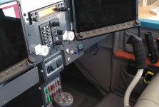
Any chance you are willing to pull the 4 screws that hold in your MFD and gets some pics of the stack from the side and maybe the rear?
Did they work with the existing center panel or did they make a new one?
.Any chance you are willing to pull the 4 screws that hold in your MFD and gets some pics of the stack from the side and maybe the rear?
Did they work with the existing center panel or did they make a new one?


IMC in Classic RV12.
This panel uses 15 amps which leaves very little room for expansion. I tried not to change much of the basic RV12 VFR electrical system. To accomplish this, a modified Z14 electrical system, based on the book AeroElectric Connection, was added to the RV12. Expanding the power budget was done by adding a B&C 30amp pad mounted alternator on my Rotax 912ULS. I ditched the stock battery and added two EarthX batteries behind the baggage bulkhead. The new alternator fed a new bus (Bus 2) and charged one of the new EarthX batteries. The Rotax 20 amp alternator charged the other EarthX on the original Bus (Bus 1). A crossover switch allowed either battery or alternator to be used for running the whole system in case of a failure. In normal operation the two busses are separated. Offloading one of the G3X screens to Bus 2 allowed enough power budget to add a Garmin GPS 175 to Bus 1. A GAP 26 heated pitot tube, MGL N16 VOR/LOC/ILS with a Razor Head was added to Bus 2. The MGL supplies VOR and ILS green needles on my G3Xs and made the 12 ready for my IFR training and IMC.
The gear box must be removed and a gear kit, available from Rotax, must be installed. The B&C pad mounted alternator will play havoc with all the engine temperature sensors in warm weather. Adding a 3/8” ring terminal to each sensor and connecting it directly to the Garmin GEA 24 Lo for each sensor solved the issue. Vans did not use these grounds on the ULS.Can you provide more detail on what it took to install the heated pitot? In planning out what it would take to get my RV-12 IMC-ready, this was always my biggest stumbling block, as it would require modifying the wing connections and so forth.
For the secondary alternator – what was required to get it hooked up to the gearbox? On my engine, I currently see a plug where the pad mount would go, but looking at the Rotax docs, I've been unable to determine if I'd also need to swap out the engine housing.
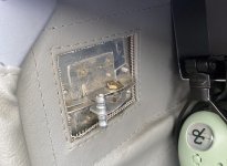
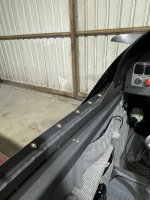
Nice finish to the interior canopy. Thanks for taking the time to do thisI was playing around with the 3D printer and made nut covers for the canopy bolts, kinda cleans it up a bit. I have a hex hole to accept the nut and they fit tight but still might use a dab of RTV. I'm still working on the print parameters. It will take 56 to do all the visible screws, weight gain 1/2 ounce.
NiceI was playing around with the 3D printer and made nut covers for the canopy bolts, kinda cleans it up a bit. I have a hex hole to accept the nut and they fit tight but still might use a dab of RTV. I'm still working on the print parameters. It will take 56 to do all the visible screws, weight gain 1/2 ounce.
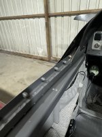
I finished the design and have shared the process and files at my blog at https://waltsrv12.com in the "Fun Stuff" tab Canopy Nut Covers.I was playing around with the 3D printer and made nut covers for the canopy bolts, kinda cleans it up a bit. I have a hex hole to accept the nut and they fit tight but still might use a dab of RTV. I'm still working on the print parameters. It will take 56 to do all the visible screws, weight gain 1/2 ounce.
I finished the design and have shared the process and files at my blog at https://waltsrv12.com in the "Fun Stuff" tab Canopy Nut Covers.

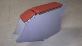
Besides the cost, the Vans trim is only to cover the front nuts, nothing for the rear edge of the canopy or behind the seats.Y'all probably know about this, but you could install these babies. I have them to install, and they're fiberglass. You trim, paint, and glue in place.