The problem is not so much that the pressure readings are high but they they are high in illogical ways. Pressure should go down as the oil temp goes up. When things are inconsistent or not demonstrating normal behavior it can be a sign that something is wrong. Ignoring it may mean problems later - like in flight at night or over hostile terrain.
A bypass may be stuck shut, oil galleries clogged or just a bad sender or gage. Why not figure it out?
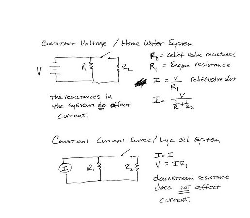
I just read the article rocketbob attached and I think there is a flaw in their logic. Higher oil pressure does not necessarily mean more oil flow. After all, the oil pump is a positive displacement pump and will only put out a fixed volumetric flow rate of oil that only varies with the rpm of the engine. Change the pressure all you want but oil flow in total will remain the same.
Here's how I believe the oil system works based on reading a lot of sources, looking at the drawings, 6 years experience operating things with pressure feed oil systems, an ME degree, a PE license and 27 years as an engineer. It does not mean I'm right, but it does mean I am not shooting from the hip!
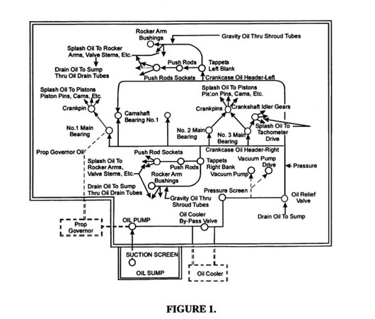
There are a couple of alternative paths for oil. One is to the oil cooler, and this flow is regulated by the "Oil Cooler By-Pass Valve" (aka Vernatherm) operation. The second is the "Oil Relief Valve" which on some engines is adjustable. It lets some oil go back to the sump to limit the oil pressure. The third is the oil filter bypass which sends oil around the oil filter when there is a large pressure drop across it. This could be caused by the filter being clogged or maybe when the oil is very cold.
In the case of the Vernatherm and the Oil Filter Bypass the total flow through the engine stays the same. The relief valve sends oil back to the sump, so if it is open, less oil will go through the engine galleries and bearings and lifters (oh my!) etc.
Note that all of these "regulators" are between the oil pump and the first engine component being cooled/lubricated by the oil, and also note according to the Lycoming diagram the oil pressure reading is downstream of all of these devices but before the cooled/lubricated engine components. This means that downstream of the relief valve the only things that affect oil pressure is oil temperature (because it affects viscosity and frictional losses) and clogged oil passages. Temp up, pressure drops. Clogs up, pressure rises. In neither case is total oil flow through the engine affected. Anything that does not go to the sump through the relief valve will go through the engine.
When the oil is cold the friction losses through the oil passages and oil cooler and filter and lines is high. The pump, since it is a positive displacement pump, will raise its discharge pressure high enough to put out the required volume of oil. If the pressure is higher than the relief valve setting some oil will go back to the sump rather than through the engine. Cold oil also leaves the Vernatherm open, bypassing the oil cooler and also reducing pressure since the cold oil is not being forced through the tight curving passages (and longer path) of the oil cooler.
As the oil warms up, the frictional losses drop and the pump does not have to raise the pressure as far to pump the constant volume of oil. As the pressure drops the relief valve will close. Once fully closed, further rises in oil temperature will reduce friction losses (aka back pressure) and the pressure out of the pump will drop further which
should be seen on the oil pressure gage, at least when it is connected at the normal spot for most RV's - at the accessory case. Also as the oil temperature comes up the Vernatherm extends, closing off the bypass and forcing oil through the oil cooler. Now as temperature starts being regulated, oil viscosity is also being regulated which also helps stabilize oil pressure. Note though that none of these pressure changes affects the volume of oil going through the engine. The only two things that affect it are engine speed (therefore pump output volume) and the relief valve being open or shut.
Setting the relief valve higher will not cause oil pressure to be higher with warm oil like BruceMe is experiencing. Any relief valve set point higher than the total pressure loss through the engine at operating temperature will not cause more oil to flow through the engine because the relief valve will be shut. The only operating region where the higher relief valve setting helps is when the oil is very cold.


")