MikeinPhoenix

Well Known Member
Patron
I just installed a new G3X system with all new Garmin LRUs for instrument flight. During an initial check-out flight, the entire system went down with red X’s everywhere on both G3X displays. AHRS stayed alive via the backup RS-232 interface, but both COMs went dead as well as the GEA24. The failure lasted for 5 minutes and slowly everything came back online. Fortunately, I wasn’t talking to ATC and was VFR at the time. BUT, it would have been very unpleasant if I was talking to ATC or was flying in IMC. I also have a G5 backup, but losing communication radios would be a big problem. Is there any way to keep the com radios working even if the CAN bus fails?

Thanks, Mike

By the way, the problem was a cold solder joint at the Garmin autopilot servo.
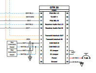
For us to really understand & analyze - would you share a dwg of the system architecture and model of the radios & audio panel & GPS navigator etc.. Single point failures, as this appears to be, should not be possible... and I'm sure G3expert's will be interested.
 
I just installed a new G3X system with all new Garmin LRUs for instrument flight. During an initial check-out flight, the entire system went down with red X’s everywhere on both G3X displays. AHRS stayed alive via the backup RS-232 interface, but both COMs went dead as well as the GEA24. The failure lasted for 5 minutes and slowly everything came back online. Fortunately, I wasn’t talking to ATC and was VFR at the time. BUT, it would have been very unpleasant if I was talking to ATC or was flying in IMC. I also have a G5 backup, but losing communication radios would be a big problem. Is there any way to keep the com radios working even if the CAN bus fails?

Thanks, Mike

By the way, the problem was a cold solder joint at the Garmin autopilot servo.
Let me guess, can bus splice using a solder sleeve?
A single panel mount com 1 (or navigator with com), and a remote on the can bus as com 2 is a good idea to avoid this issue.
 
Let me guess, can bus splice using a solder sleeve?
A single panel mount com 1 (or navigator with com), and a remote on the can bus as com 2 is a good idea to avoid this issue.
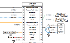
Walt, you guessed exactly right on the can bus solder sleeve. Coincidentally, I actually have the very set-up you recommended….a panel mount com1 and a Garmin remote com as Com2. Both were X’d out during the can bus failure.

I've snipped the portion of the overall wiring schmatic that addressed the COM1 and COM2 wiring detail.

1715659470717.png
1715659546329.png
 
Last edited:
Walt, you guessed exactly right on the can bus solder sleeve. Coincidentally, I actually have the very set-up you recommended….a panel mount com1 and a Garmin remote com as Com2. Both were X’d out during the can bus failure.

I’ll try to paste the relevant portion of the wiring schematic per the above request.
Does the panel mount have an operator interface? If so, how was it’s interface affected by a CAN Bus failure?

Also, just how is the solder sleeve installed? Is it a solder sleeve on the CAN Bus wires or just the shields?

Solder sleeves are awesome if properly applied and installed not so much if not! If you do not see the solder flow, they will fail! One guy I know tried using a hair dryer to install them. 😳
 
Last edited:
Walt, you guessed exactly right on the can bus solder sleeve. Coincidentally, I actually have the very set-up you recommended….a panel mount com1 and a Garmin remote com as Com2. Both were X’d out during the can bus failure.

I’ll try to paste the relevant portion of the wiring schematic per the above request.
Solder sleeves were NOT designed for soldering wire connections, they are for shielded cable termination despite what some folks think/use them for.
The fact that the com was X’d out on the G3X doesn’t prevent you from ‘manually’ tuning it. Actually not sure why you would have a panel mount com/nav taking up valuable data bar space on the G3X.
 
Solder Sleeves were designed for a variety of wire splicing applications and have been used in NASA hardware for many years. They do require some attention to detail and are not created equally. They also require a proper heat source. An excellent article with real world quantitative tests was published in Kitplanes.

 
Last edited:
This thread got me thinking about COM redundancy. I am prepping to start installing avionics now. I will have a panel mount COM with a remote GMA245R Audio Panel. If my G3X display were to go down for some reason what happens to the Audio Panel? Is there a way to force the GMA245R to fail to or manually switch it to COM1? What would happen if I pull the audio panel circuit breaker? Would that fail to COM1 by default? I have volume controls on the panel radio.
 
Solder Sleeves were designed for a variety of wire splicing applications and have been used in NASA hardware for many years. They do require some attention to detail and are not created equally. They also require a proper heat source. An excellent article with real world quantitative tests was published in Kitplanes.

They will continue to be source of connection problems due to the inability of most folks to properly install/inspect the joint for proper flow/wet out of the solder. Cold joints are common when using solder sleeves (easy to see flow when used as shield terminations but not so much when splicing)

Don't really care what "NASA" does in their factories (they have had their problems, Appollo 1 & 13 come to mind), but in my world they will never be used to splice wires. FWIW, I don't recall every seeing a repair method in the airlines that used them to splice wires (I've worked as an avionics engineer, bench/black-box/aircraft avionics repair tech and had quite a bit of training in these areas).

As far as the Kitplanes article, nice try but not really doing anyone any favors.
 
Last edited:
This thread got me thinking about COM redundancy. I am prepping to start installing avionics now. I will have a panel mount COM with a remote GMA245R Audio Panel. If my G3X display were to go down for some reason what happens to the Audio Panel? Is there a way to force the GMA245R to fail to or manually switch it to COM1? What would happen if I pull the audio panel circuit breaker? Would that fail to COM1 by default? I have volume controls on the panel radio.
If you pull power to the GMA it defaults to com 1. That's why com 1 should always be the panel mounted unit.
 
Forgive me for being a little blunt but having 2 radios and making them both remote makes your system vulnerable to exactly the type of failure you describe. It is always worth carrying out even a basic failure mode analysis. You should not allow any one failure to take out both radios, be that a power supply or other failure. The easy method is to make one radio (or nav/com) a panel mount. It may challenge your panel layout but it is the only sensible way ahead. Making the panel mount com1 at the audio panel will mean the pilot's headset is connected directly to com1 in the event of a power or connectivity failure.
 
Forgive me for being a little blunt but having 2 radios and making them both remote makes your system vulnerable to exactly the type of failure you describe. It is always worth carrying out even a basic failure mode analysis. You should not allow any one failure to take out both radios, be that a power supply or other failure. The easy method is to make one radio (or nav/com) a panel mount. It may challenge your panel layout but it is the only sensible way ahead. Making the panel mount com1 at the audio panel will mean the pilot's headset is connected directly to com1 in the event of a power or connectivity failure.
He has one panel mount GTR 200 and one remote GTR 20.

A failure of the CAN bus should not have taken out the local controls on the panel mounted GTR 200. Ignore the red X's on the G3X screen and use the radio's built in controls.
 
He has one panel mount GTR 200 and one remote GTR 20.

A failure of the CAN bus should not have taken out the local controls on the panel mounted GTR 200. Ignore the red X's on the G3X screen and use the radio's built in controls.
And let me add a note of clarification (and admit some embarrassment). This was a first test flight of a new instrument panel when the CAN bus system failed and everything on the G3X screens showed red X’s. I was so focused on analyzing the screens and the various messages popping up on the G3X that I didn’t look at the panel mount GTR 200 display to confirm it was still operating properly. Based on the comments here, it very likely was ok (which provides some comfort going forward).
 
And let me add a note of clarification (and admit some embarrassment). This was a first test flight of a new instrument panel when the CAN bus system failed and everything on the G3X screens showed red X’s. I was so focused on analyzing the screens and the various messages popping up on the G3X that I didn’t look at the panel mount GTR 200 display to confirm it was still operating properly. Based on the comments here, it very likely was ok (which provides some comfort going forward).
On the plus side, it led me to a very helpful Kitplanes article!
 
And let me add a note of clarification (and admit some embarrassment). This was a first test flight of a new instrument panel when the CAN bus system failed and everything on the G3X screens showed red X’s. I was so focused on analyzing the screens and the various messages popping up on the G3X that I didn’t look at the panel mount GTR 200 display to confirm it was still operating properly. Based on the comments here, it very likely was ok (which provides some comfort going forward).
Been there done that many times! Aviating takes priority over communicating!
 
They will continue to be source of connection problems due to the inability of most folks to properly install/inspect the joint for proper flow/wet out of the solder. Cold joints are common when using solder sleeves (easy to see flow when used as shield terminations but not so much when splicing)

Don't really care what "NASA" does in their factories (they have had their problems, Appollo 1 & 13 come to mind), but in my world they will never be used to splice wires. FWIW, I don't recall every seeing a repair method in the airlines that used them to splice wires (I've worked as an avionics engineer, bench/black-box/aircraft avionics repair tech and had quite a bit of training in these areas).

As far as the Kitplanes article, nice try but not really doing anyone any favors.
Walt and I rarely agree on much, but here I’m with him. I have never used Solder Sleeve on any of the panels I built.

I do not understand the attraction of Solder Sleeve. If you can build a plane you can make a proper solder joint. Add shrink tubing to immobilize the joint from relative motion then move on.

Carl
 
On the plus side, it led me to a very helpful Kitplanes article!
I’d actually forgotten about that artcile - Dave did a great lookign at the topic objectively and with some science. As with anthing (soldering or crimping), if you don‘t do it right, you won’t get good results!
 
I guess I never knew any better. As a Kid I worked for Bendix doing electronic fabrication on hardware built to NASA specifications. Solder sleeves were an acceptable splice and preferred in many cases. It is a proper solder joint with the proper solder and flux with shrink tubing. What’s not to like?
 
Last edited:
My own experience on this follows. I must have used 100+ raychem solder sleeves on our RV, almost exclusively for draining shielding. I had a small number of them fail in a very interesting way. The solder flowed out normally but didn't penetrate the solder drain wire. But that fact was not very evident from looking at the shrunk sleeve from the outside. I only learned this was possible when a shield drain wire pulled out in my hand with minor force applied to it.

I suspect some contamination of the wire on the shield drain prevented wetting the wire in these cases. But the lack of observability made me decide to avoid solder sleeves for splices. I think I can do a more reliably consistent job with traditional solder and heat shrink tubing.

I'm sure some pro-level person can make these work with perfect reliability, but that person wasn't me.
 
I just installed a new G3X system with all new Garmin LRUs for instrument flight. During an initial check-out flight, the entire system went down with red X’s everywhere on both G3X displays. AHRS stayed alive via the backup RS-232 interface, but both COMs went dead as well as the GEA24. The failure lasted for 5 minutes and slowly everything came back online. Fortunately, I wasn’t talking to ATC and was VFR at the time. BUT, it would have been very unpleasant if I was talking to ATC or was flying in IMC. I also have a G5 backup, but losing communication radios would be a big problem. Is there any way to keep the com radios working even if the CAN bus fails?

Thanks, Mike

By the way, the problem was a cold solder joint at the Garmin autopilot servo.
GEA can (and should) have a RS-232 backup as well as the GSU25. With A CAN failure the info will show only on the GDU that is wired so it would make sense to RS-232 the GSU & GEA to the GDU that normally displays that info.
Too bad the GTR20 didn't have a RS-232 backup.