rynmss

Member
I'm having a hard time envisioning a battery backup system in addition to an endurance bus. I'm largely running with Z-11 (Aeroelectric Connection). I have an IBBS system as well. So in my system, panel wise, I'd have (among others):

Switch: Master - On/Off
Switch: Battery/Aux - On/Off
Switch: E-Bus - On/Off

The master is on until a need arises, then master goes off, and E-bus goes on. We run off the E-bus until a) landing and need full systems until touchdown at which point E-bus goes off and master comes back on, or b) things really descend (unfortunate pun) and either the backup kicks in due to low voltage or I kick it over via the switch and we run on that until lights go out.

Does this sound correct?

Is there a concern with the IBBS sense wire being on the E-bus after the voltage drop of a diode?


Now, while we're up in the hypothetical air in my failing plane, I also have an alt. field breaker, which in my scenario I've pulled, removing charging current from the system. Having this breaker is the equivalent of:

Switch: Master - Alt/Batt/Off

Correct? Where the three position switch reserves the middle position to remove the current going to the alternator field?


Much appreciate anyone who can help shed some light here, and thank you in advance.
 
I just run with my ebuss on all the time. One less switch to throw. Master is Off-Bat-Alt as you suggest. I have no breakers, all ATC fuses in baggage compartment.
 
I just run with my ebuss on all the time. One less switch to throw. Master is Off-Bat-Alt as you suggest. I have no breakers, all ATC fuses in baggage compartment.

How do items on the E-bus get shut down in order to prevent draining the battery? I'm familiar with an always on bus, but these would typically be manually switched items, yes? The endurance bus could contain things that would draw down the battery if not disconnected via switch or some other means.

I, too, am working with primarily fuses, but had a few exceptions: P-mags and alt field, though I'm not opposed to rethinking the latter.
 
Could I suggest you should write down the goals you aim to achieve in one line statements - it may take a little time until you have that sorted.
Then look at your system and figure out how your system achieves those goals.
What happens after any one failure? No point in looking at 2 failures, you will land as soon as practicable after any one failure.
Do you need an E-bus, IBBS and a back-up battery to achieve your reliability goals?
Can you tolerate the complexity that multiple back ups brings?
 
How do items on the E-bus get shut down in order to prevent draining the battery? I'm familiar with an always on bus, but these would typically be manually switched items, yes? The endurance bus could contain things that would draw down the battery if not disconnected via switch or some other means.

I, too, am working with primarily fuses, but had a few exceptions: P-mags and alt field, though I'm not opposed to rethinking the latter.
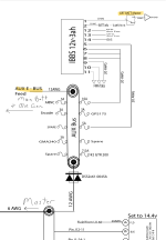
Z11 has everything you need. Just add the IBBS with a switch like the diagram below. Here is what I have and my power up sequence.

IBBS switch on - powers two GRT sport EX screens and the GRT EIS.
AUX Bus switch on - powers E bus devices, charges IBBS, plus pass thru power to GRT devices.
Master switch on - powers everything, plus E bus, charges IBBS and pass thru power to GRT devices.

I also have an engine bus because of my dual SDSEFI but that’s another story.

1716724277904.png
 
How do items on the E-bus get shut down in order to prevent draining the battery? I'm familiar with an always on bus, but these would typically be manually switched items, yes? The endurance bus could contain things that would draw down the battery if not disconnected via switch or some other means.

I, too, am working with primarily fuses, but had a few exceptions: P-mags and alt field, though I'm not opposed to rethinking the latter.
The only things on my e-buss that don't have an integral switch are my GTN-650, both EFIS and their associated AHRS and magnetometer, the A/P. All other avionics has an internal switch. The EFIS each have a switch in the switch panel which powers down their associated equipment also.
 
Z11 has everything you need. Just add the IBBS with a switch like the diagram below. Here is what I have and my power up sequence.

IBBS switch on - powers two GRT sport EX screens and the GRT EIS.
AUX Bus switch on - powers E bus devices, charges IBBS, plus pass thru power to GRT devices.
Master switch on - powers everything, plus E bus, charges IBBS and pass thru power to GRT devices.

I also have an engine bus because of my dual SDSEFI but that’s another story.

View attachment 63514
This is helpful!

A couple of questions:
  • Have you had any issues with the voltage sensing placed after the diode on the aux bus? That would have the ibbs sensing 1.2v below the actual, wouldn’t it?
  • Is the aux E-bus feed switched? Assuming an on/off on the panel?
 
This is helpful!

A couple of questions:
  • Have you had any issues with the voltage sensing placed after the diode on the aux bus? That would have the ibbs sensing 1.2v below the actual, wouldn’t it? No issues (240 hrs)
  • Is the aux E-bus feed switched? Assuming an on/off on the panel? Yes
click to expand. Answers in red.

Look up John Bright on this forum. I have a version of his electrical diagram. All of your power and alternate feed switches should be on during flight. You do need a warning light or audio for low volts/alterator failure. Preferably both.
 
All of your power and alternate feed switches should be on during flight.
+1

Minimizing required pilot input under pressure is a key design goal. Perfect is "everything necessary to flight just continues to work".
 
… Have you had any issues with the voltage sensing placed after the diode on the aux bus? That would have the ibbs sensing 1.2v below the actual, wouldn’t it?
The DSS2x61-0045A would drop ~0.5V in this case. I believe I am being conservative in assuming junction temperature 125C and 20A.
 
This is helpful!

A couple of questions:
  • Have you had any issues with the voltage sensing placed after the diode on the aux bus? That would have the ibbs sensing 1.2v below the actual, wouldn’t it?
  • Is the aux E-bus feed switched? Assuming an on/off on the panel?
The GRT equipment I have has multiple power inputs. I use two of them, one on the non-Ebuss side, and one on the ebuss.

I definitely saw voltage sensing issues when I only had power from the ebuss side. There's the voltage drop from the diode of course, but the GRT internal voltage sensing always read low as well, and I checked the voltages at the connectors, it simply read low.