Trying my luck on this forum.
Looking for help with DIY 3D scanning software.
I have an somewhat unfinished wood prop from 2007 that is rather grossly out of balance. Requires some 60 grams (more than 2 oz) on a prop bolt near blade to get somewhat in static balance. It's lso out of balance at right angle to prop blade axis. If I got it right maple weighs about 0.4oz/cu in. So I need to remove something on the order of 4 cu in on and near the heavy blade hub. I realize that the shape under the spinner is not aerodynamically important and I could just drill a 1/4" hole and fill it with carbide rods. However, seems like a band-aid solution, not handling the root cause of the static imbalance.
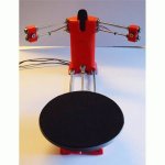
So my idea is to mount the prop on an old PSRU (reduction gear drive). Mount a DIY 3D scanner (see attached picture -- less turntable) on a bar above one blade. Take a profile snapshot, rotate the prop 180 degrees and take a new snapshot of the other blade. Comparing the two pictures should clearly show the profile differences on a 2D plot on a laptop at the chosen prop radial. This can be repeated along the prop blade, from hub center all the way out to the tip, by moving the 3D scanner a bit on the bar.
I should then be able to grind and sand down the heavy hub side and prop with confidence.
So, does anyone have experience with DIY 3D scanning software and can point me in the right direction?
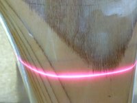
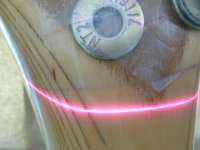
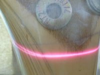
I've searched for USB camera data output format but not found any useful hits. Basically I need to subtract or compare two pictures, isolate and measure distance between the two laser lines.
Finn
Looking for help with DIY 3D scanning software.
I have an somewhat unfinished wood prop from 2007 that is rather grossly out of balance. Requires some 60 grams (more than 2 oz) on a prop bolt near blade to get somewhat in static balance. It's lso out of balance at right angle to prop blade axis. If I got it right maple weighs about 0.4oz/cu in. So I need to remove something on the order of 4 cu in on and near the heavy blade hub. I realize that the shape under the spinner is not aerodynamically important and I could just drill a 1/4" hole and fill it with carbide rods. However, seems like a band-aid solution, not handling the root cause of the static imbalance.
So my idea is to mount the prop on an old PSRU (reduction gear drive). Mount a DIY 3D scanner (see attached picture -- less turntable) on a bar above one blade. Take a profile snapshot, rotate the prop 180 degrees and take a new snapshot of the other blade. Comparing the two pictures should clearly show the profile differences on a 2D plot on a laptop at the chosen prop radial. This can be repeated along the prop blade, from hub center all the way out to the tip, by moving the 3D scanner a bit on the bar.
I should then be able to grind and sand down the heavy hub side and prop with confidence.
So, does anyone have experience with DIY 3D scanning software and can point me in the right direction?
I've searched for USB camera data output format but not found any useful hits. Basically I need to subtract or compare two pictures, isolate and measure distance between the two laser lines.
Finn