What's new
Van's Air Force

Don't miss anything! Register now for full access to the definitive RV support community.

Undervolt Situation

petehowell

Well Known Member
I need some help from the hive-mind......

RV-9A with 2700 hours. Coming back from fly in on Sat morning, noticed that Bus voltage was variable from 13.4 - 13.8. It's normally 14.1 - 14.3.

Equipment
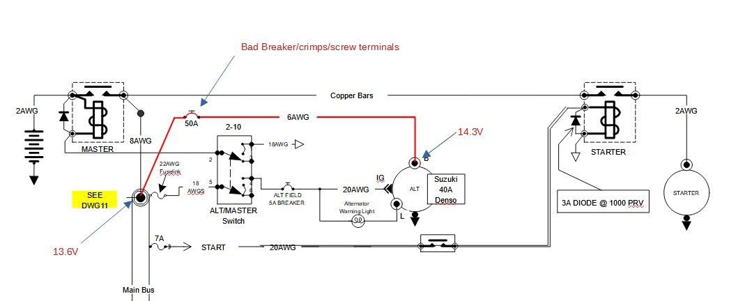
- 87 Samurai 40 amp Int Reg alternator (this is #3 -they seem to last 800-1000 hrs)
- PC680 Battery 5ish yrs old
- 60 amp P&B breaker b/t the Alt B term and the main buss

Things I have done:

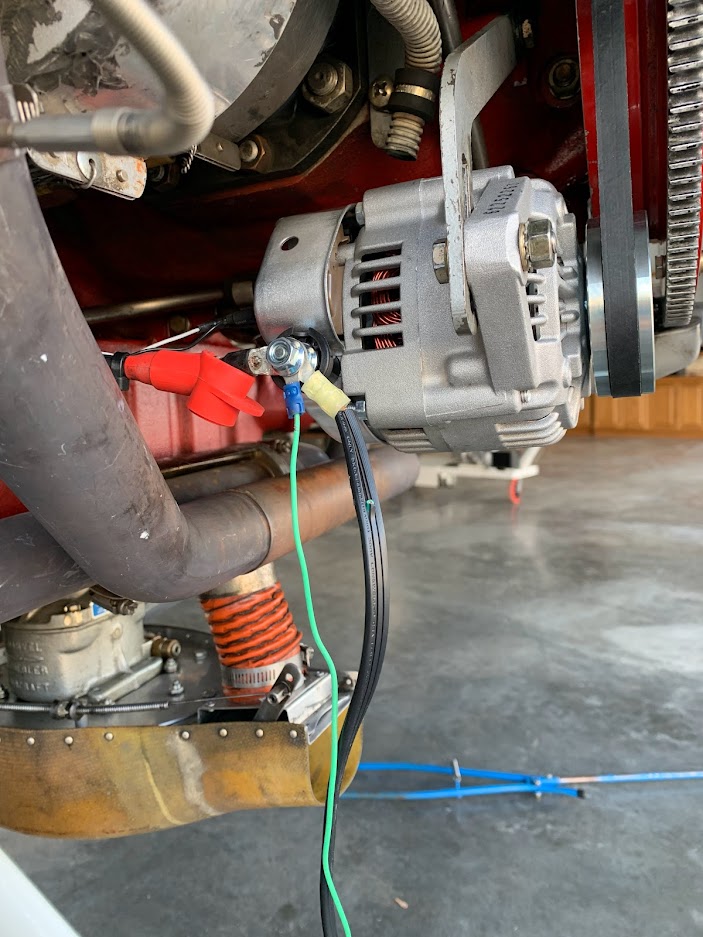
- Verified bus voltage at the F term on the alternator 12.8 with engine off
- snugged up the terminals in the ALT plug - they are tight(Just using the F and L terminal of the 3 prong plug.
- Swapped alt for a known good unit - no change
- Tested the battery at the parts store - passed as an AGM Batt with 220 CCA it is 12.7-12.8 at rest
- swapped out the battery for an older one that holds a charge well - no change. Battery connections are tight
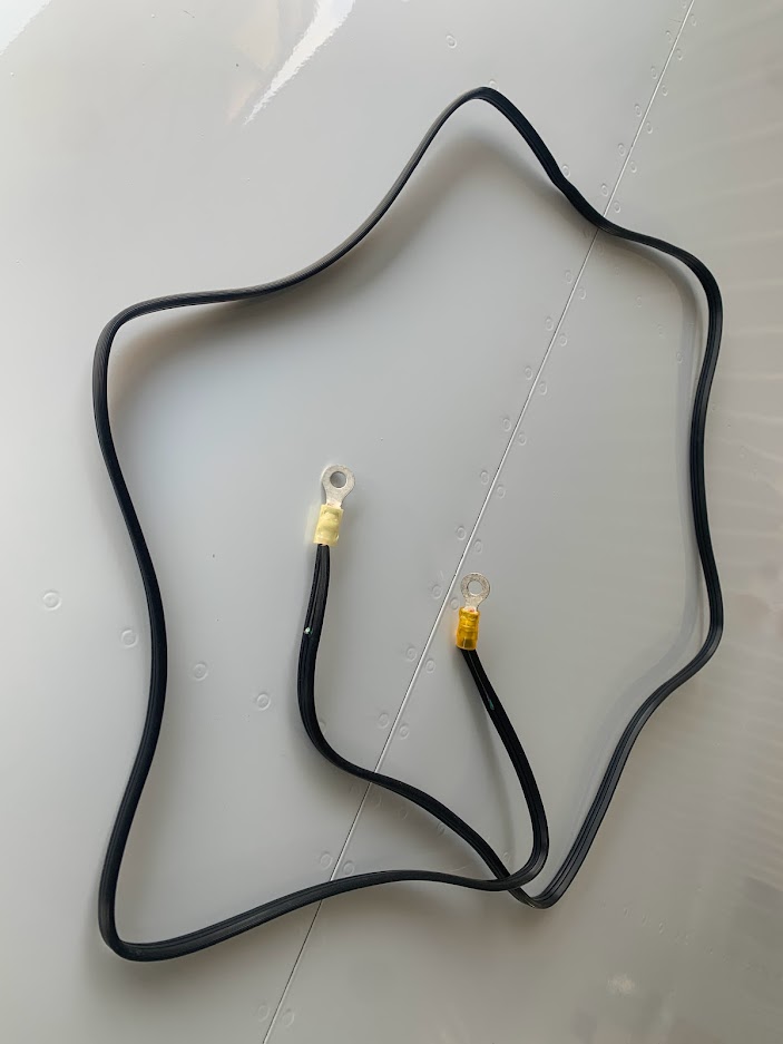
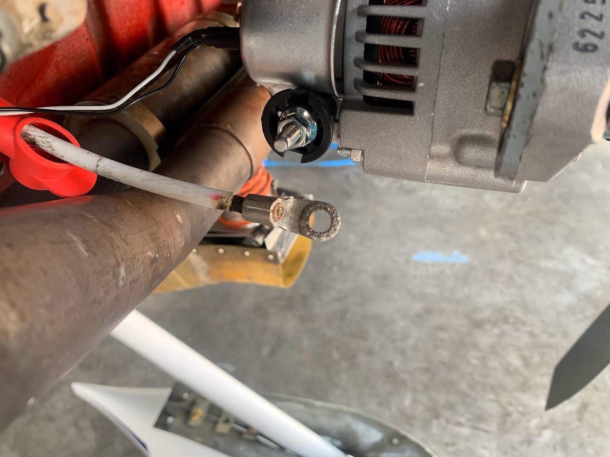
- Ran a lead from the B term of the Alt to the cockpit - with engine running it is a solid 14.3 volts
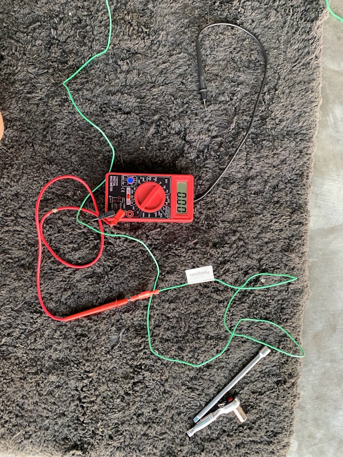
- Used a VOM to verify the bus voltage actually is 13.4-13.6 volts (it is)
- Chased connections from the alt to the breaker and bus they seem to be solid(did not disassemble and clean any of them)
- Flew it near the field tonight - Same voltages, but noticed if I turned the lights on, the voltages actually would go up a bit to 13.8 and then return to ~13.6. However, if I then, shut off all the lights, the voltage would run up to 14.2 and stay there for a few min, then migrate back down to 13.6. Also, when I landed and shed the lights, AP and TPX, the volts would climb back above 14 for bit.
- Checked Voltage drop across the main contactor - negligible - snugged up the connections for giggles - nothing was loose.
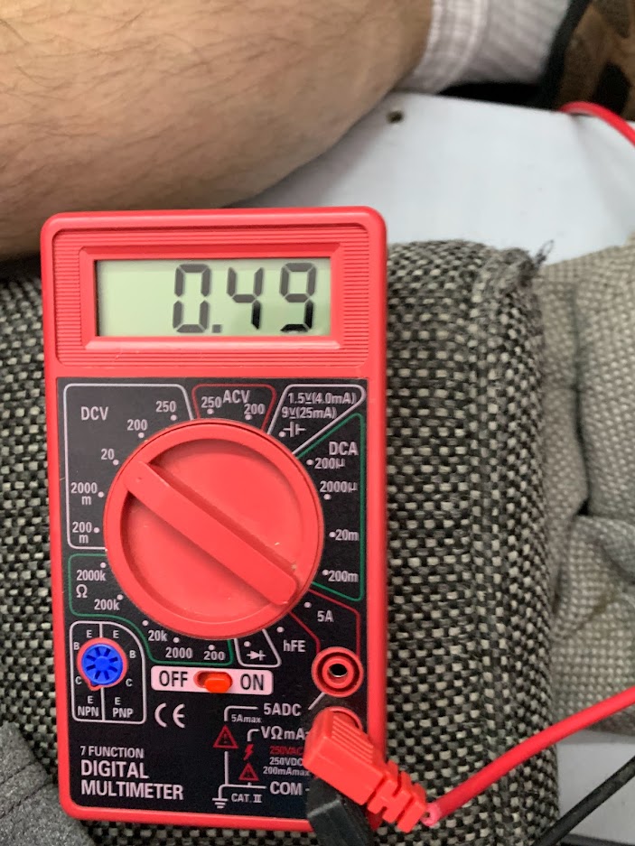
- Checked voltages on both side of the 60 amp breaker they were same as bus volts. If i pulled the breaker while at idle - the volts on the feed side went to about 15.2 (I know this is not great for the alternator)
- Checked Ohms across the 60 amp breaker - negligible.


Thoughts:

- Alternator seems good - 14.3 at the output terminal
- There seems to be something causing a big load on the main bus, the battery comes to mind. I don't mind replacing it, but it does seem to be good, and had same behavior using 2 diff, albeit older batteries
- Bad connection? Undo and clean all the connections.
- Replace the 60amp breaker again - maybe it goes high resistance under high load?
- Replace the Master contactor

I'm kinda lost here - any thoughts appreciated!
 
If there is truly a voltage drop between the output post and the bus, AND voltages are both measured to a common ground point, then there is loss, and that is making heat. It is resistance somewhere. That can be measured by a voltage across a suspected device, but don't overlook formally good terminal crimps. Assume nothing and measure anything/everything that is suspected.

I have a thermal camera that picked up a warm extension cord end by accident in the hangar, if you have one that could me used in lieu of voltage drop.

Don't think it is a battery. It may be the regulator (or other internal fault) but an independent and simultaneous voltage is required to eliminate other possibilities.

Just a few fuzzy late evening thoughts. Good Luck, and nice presentation of findings.
 
Main solenoid

Left field idea. Too much pitting on the main solenoid causing the buss to draw too many amps across it causing it to heat and drop voltage?
 
I had almost identical situation with my now 22 year old 8. It was built as a basic VFR plane with minimal electronics and avionics. Over the years it accumulated a bunch of upgrades. Mostly rewired the entire plane.
When my voltage eased down like yours I chased all the usual suspects like you have. I ended up replacing the main feed wire from Alternator, (ND also) and stepping up one wire size. Fixed everything.
Old wire was corroded and black inside insulation. Resistance was high.
Just a thought, but that was my problem.
 
Matches a local suggestion

Left field idea. Too much pitting on the main solenoid causing the buss to draw too many amps across it causing it to heat and drop voltage?

Fair thought - I have a new one arriving today. It had no voltage drop with just the battery energizing it, but it was not flowing the ALT current, and this unit has been on for about 1000 hours now.
 
I had almost identical situation with my now 22 year old 8. It was built as a basic VFR plane with minimal electronics and avionics. Over the years it accumulated a bunch of upgrades. Mostly rewired the entire plane.
When my voltage eased down like yours I chased all the usual suspects like you have. I ended up replacing the main feed wire from Alternator, (ND also) and stepping up one wire size. Fixed everything.
Old wire was corroded and black inside insulation. Resistance was high.
Just a thought, but that was my problem.

Jerry - could you measure the high resistance before replacement? I'm at almost 17 years - this is a possibility.
 
What is the Lester # for that alt? They are 5 numerals. Is it internally or externally regulated? Interesting that you get the correct 14.x at the B lead, which means all is healthy with the Alt and VR. The voltage bouncing on loads going on/off further points to a working alt and VR. Yes, a dead cell on a Batt can sap a lot of juice and drop the volts accordingly, but that is somewhat rare on a battery with a resting voltage of 12.8. You may even be able to hear it, as the Alt will be running at 100%,run hot, and die an early death. Most any decent batt tester will identify a bad cell. However, they can trick you sometimes as when cold all is good and when they get hot and expand will open the cell. However, you would be seeing difference in the volts when hot vs cold. Have you checked the ground strap? Pull both sides off and clean the mating areas. Then with the engine at idle, measure voltage across both sides of the strap (voltage drop). Try physically moving the strap around while measuring. Also get and ohmeter probe on the alt case and another on the airframe ground and confirm .1 or less ohms. getting 14.3 between B lead and Alt case only means things are good at Alt. Can also put red probe on B lead and Black probe on airframe ground (not the eng ground) and note the difference from the previous 14.3 with engine running. Problems identified in this way will then be isolated to the ground side. Assuming the B lead goes to the batt, pull that and both of the batt terminals and clean them and reinstall. Corrosion or looseness can cause this.

Once you fully confirm the ground side, you will need to start tracking the positive side. WIth the engine running, start taking voltage measurements originating at the alt and then checking EVERY connection point down the line from there to the voltage reading instrument. At some point you will find a lower voltage and will narrow your search. If you don't like the idea of doing it with the engine on, pull the B lead wire off the alternator and connect it to the Red clamp on the batt charger and put black clamp on the alt frame. This emulates a running alternator. Do this with the master on so there is a load for the charger.
 
Last edited:
Left field idea. Too much pitting on the main solenoid causing the buss to draw too many amps across it causing it to heat and drop voltage?

The electron flow from the Alt to the buss never crosses over the contacts in the master, or at least it shouldn't. What you describe would reduce current to/from the battery and present as sluggish starter performance and possibly a battery that would struggle to fully charge. OP states 12.8 resting batt voltage, which is near 100% for lead acid. If wired as most RVs are, these contacts cannot be the cause.
 
Last edited:
Jerry - could you measure the high resistance before replacement? I'm at almost 17 years - this is a possibility.

Very easy to test. Start engine and measure voltage at B lead, then measure voltage where that wire terminates (likely a shunt or the post of one of the two solenoids.
 
Like others have stated, the battery and battery contactor are not the problem.
While the engine is running, the electrical system is powered by the alternator, not the battery.
Since the alternator "B" lead and the main bus are connected together, they should both be at the same voltage.
Since they are not, that means there is resistance between them.
Do NOT use an ohmmeter because it is not very accurate at measuring low ohms.
Instead, use a voltmeter to determine where the voltage is being dropped.
For testing purposes with the engine off, leave the master switch off, then
connect a jumper wire between battery positive and the alternator "B" terminal.
Then check for voltage drops between alternator "B" terminal and main power bus.
There won't be any voltage drop unless current is flowing. So turn on many electrical loads while testing.
 
Jerry - could you measure the high resistance before replacement? I'm at almost 17 years - this is a possibility.

After all the head scratching we just decided to replace the wire. I don’t remember measuring the resistance even after looking at how black the inside of the wire was..
 
Last edited:
After all the head scratching we just decided to replace the wire. I don’t remember measuring the resistance even after looking at how black the inside of the wire was..

And although maybe not related, snugged up the bolts on the contactors.
 
Lunchtime Thoughts

Here is my setup, I'm thinking that I have 2 6AWG wires, 4 crimps/wire ends, 4 screw connections, and one breaker that could be causing the voltage drop between the B terminal on the ALT and the Main Bus.

See stuff in red - am I making sense here? Thanks for the help! I'll report from the hangar tonight.

AJFCJaUYO1XgruGcyLmD61_Lp08qWNiI8oL2wutCpnRGDSexkolUVAAtfk8Euz_wLk9nEfwRdOcYZMxK11zoBhU3AiXCr9GOPo72OuXUxdWm9r8t7c9pkgt28Yh7jm0ZvInPaJAwri6qTJ4qIz_3Vsy_vfMf-g=w1046-h432
 
Makes sense - large wire crimps seem to be the first to get corrosion in my experience….
 
I had similar symptoms with fluctuating voltage a few years ago. It turned out water had gotten into the area where my 60 amp alternator output breaker was located and ruined it. I replaced the breaker and it's been fine since. I also had a perfectly good alternator on the shelf since that was the first place I went when troubleshooting.
 
Here is my setup, I'm thinking that I have 2 6AWG wires, 4 crimps/wire ends, 4 screw connections, and one breaker that could be causing the voltage drop between the B terminal on the ALT and the Main Bus.

See stuff in red - am I making sense here? Thanks for the help! I'll report from the hangar tonight.

AJFCJaUYO1XgruGcyLmD61_Lp08qWNiI8oL2wutCpnRGDSexkolUVAAtfk8Euz_wLk9nEfwRdOcYZMxK11zoBhU3AiXCr9GOPo72OuXUxdWm9r8t7c9pkgt28Yh7jm0ZvInPaJAwri6qTJ4qIz_3Vsy_vfMf-g=w1046-h432

Pete,

Here's a thought that might save you some time on your back with your head under the panel.

Make up a new 6 AWG wire and connect it to the alternator in addition to the existing 6 AWG wire. Connect the new wire to the switched side of the master contactor (a fuse in the end next to the contractor is optional for now).
Now, test with the new wire in place. If everything is fine, you have two options:
1. Leave the new wire in place and make sure there's a fuse near the contactor. This won't give you a functional alternator breaker on the panel, but you do have a field breaker to depower the alternator. Removal of the old wiring is your choice; if you leave it in place, place an inop sticker next to that alternator breaker.
2. Replace the existing wiring/breaker where faulty.
 
I had a similar issue. The engine to airframe ground cable had become loose and corroded in the terminal end. I cleaned and soldered the terminal, as I had no way to crimp the #2 cable. That solved the problem.
 
Solution Found

I took the collective wisdom offered here and put it to work. First, I made some tools.

A 12V jumper cable.....

AJFCJaVz0ieShI2tkSYhtRILCAhv_OInC_P1zn3SSIVdcMy8E9IrxjFpibI8X7Mo4shzDwO1XYHYz8SePgKpINPMsrapg4hlge7-mm3fNDetgBX8ArF3RU6YaAXBKdKEjbPGTw8iCmgrjT0nGGn9dCMgA3temQ=w703-h937


A $3 VOM with a long lead extension - plush shag hangar rug optional, but highly recommended!

AJFCJaWQsLLMrRCeGHd-LvAplieC34Rt2C_fasRexbxcsuaLrU4mercAD7JsxryaPWiUEnwOmR32OuGXK96sWDtnF-IwKXqT5Gzs8H57-nK_itT7M0QK8oGfZYMuCzCVP-6tp6fjg9F2JIajxUQW7JZuS0dYLA=w703-h937


Here's the alternator connection - B-lead to CB, VOM Lead, and jumper to Battery + side

AJFCJaUaWgEhskr-CHJtXSiMffFKnIS7pE5jgwxG8Dvyp7AWxqbMD6nlCTcqkW4JLY6CiynvHvoM-ef2sJrGLuhE6y3o0XWIiig1xelbnE-AFCtjUMIGVE3TrmxEajlIREM-us6k-HuP4W-7KMejqLTt1AOOPQ=w703-h937


Hooked everything up including an Odyssey smart charger and started testing. Probed the feed side of the circuit breaker and found this:

AJFCJaUjn9v5lHhIj149EgbKIcoLvb7-1EeXdCC_M0p1nN1k1heJyxCBq9EUN33OSrEV_XkD26n5VGn84M7N6YraFNrEBpczmgcZC66diQ7shmLmjPSm5nI9Zo4s2jE1m9upJvzEwicU-zbfJGVHHGBpdVQmVQ=w703-h937


Ok - it is the B-term to CB wire or one of the lugs on either end, cool. I aggressively wiggled the CB wire end with no change, so I went to the B-term Lug. It looked to be in good shape = no cracks or obvious damage, but when I peeled back the shrink tube - I saw some suspicious marks and when I probed behind the lug - Boom! 0.49V drop again. We have a winner!

AJFCJaVCh3h8BQmcpSSjs4YdLq-mguCiZY5pdx4VnFH9hvxhHYGVUQdQhYtzc7rbl_O_QPFctIfV9esixsCpm41vPzAGTQaAQfXUiaSoMpcFoUzBnwBtN8EwWYfHfLKIzBufUc8_cTkpsQMu8FK0KTkzJ5_pFA=w1249-h937


There was a bit o' slack in that cable, so I cut off the old lug and went to NAPA and got some 6AWG Lugs. The counter man needed a vehicle type for the sales order- I told him it was an off-road vehicle that really flies......

Back at the hangar, I stripped back some insulation and soldered on the new lug. Guess what? 0.0V drop at all locations now. I'll get things cleaned up and move on the next adventure.

I am thinking about remaking the cable. If so, thoughts on the super stiff tfezel vs more flexible welding cable? Also, thoughts on crimping vs soldering the lugs on?

Many thanks to all who responded with suggestions - I learned some new things and fixed my plane. Voltage drop testing is a clever tool to have in the box and I'm proof any idiot can do it. All in all, a Win - Win. At 2700hrs and 16.5 years I'm not angry at all about this repair.
 
...
I am thinking about remaking the cable. If so, thoughts on the super stiff tfezel vs more flexible welding cable? Also, thoughts on crimping vs soldering the lugs on?

...

Welding cable and crimping seem to be strongly recommended by many experts. It's what I did, and is working well, but I have 10% of the hours you have!
 
I took the collective wisdom offered here and put it to work. First, I made some tools.

A 12V jumper cable.....


I am thinking about remaking the cable. If so, thoughts on the super stiff tfezel vs more flexible welding cable? Also, thoughts on crimping vs soldering the lugs on?

Many thanks to all who responded with suggestions - I learned some new things and fixed my plane. Voltage drop testing is a clever tool to have in the box and I'm proof any idiot can do it. All in all, a Win - Win. At 2700hrs and 16.5 years I'm not angry at all about this repair.

Doubt you will find much welding cable in 6 AWG. Your failure sounds more like corossion than movement caused by a stiff wire. No need for tefzel (Tefzel's purpose is to create less toxic fumes when burned) in the cowl environment, though nothing wrong with using it there. That said, mil spec wire uses tinned copper strands, so much more resistant to corrosion and therefore likely worth the added cost. Welding cable is NOT tinned. I am a fan of soldered connections, but do not regularly use them on end terminals in a high vibration area. HOWEVER, soldered connections are vulnerable to fatigue from movement, so proper strain relief for an inch or two from the joint is critical when using that method. If you cannot keep the wire from moving near the terminal, DO NOT use solder.
 
Last edited:
Marine Cable

Hi Larry,

I found some 6awg marine battery cable with tinned strands that I am going to take a look at. I plan to make a new cable and crimp the ends.

Thanks for all the help with this fix!


Doubt you will find much welding cable in 6 AWG. Your failure sounds more like corossion than movement caused by a stiff wire. No need for tefzel (Tefzel's purpose is to create less toxic fumes when burned) in the cowl environment, though nothing wrong with using it there. That said, mil spec wire uses tinned copper strands, so much more resistant to corrosion and therefore likely worth the added cost. Welding cable is NOT tinned. I am a fan of soldered connections, but do not regularly use them on end terminals in a high vibration area. HOWEVER, soldered connections are vulnerable to fatigue from movement, so proper strain relief for an inch or two from the joint is critical when using that method. If you cannot keep the wire from moving near the terminal, DO NOT use solder.
 
Bad Solder/Crimp

Quick postmortem here on the cut off lug. My buddy Bill stopped over with his microscope and took a look. Apparently, some idiot (me) crimped and soldered the lug when the cable was built, but the solder job was not well done and the lug may have not been the right size. 17 years of hanging on that buzzing alternator finally made it go high resistance.

The boss has spoken to the worker about shoddy workmanship.

Thanks again to all who helped here.

Good to hear the boss stepped in and cracked the whip. Us worker bees can create real messes when left to our own devices.:eek:
 
Back
Top