What's new
Van's Air Force

Don't miss anything! Register now for full access to the definitive RV support community.

Z-13 with SD-8 electrical diagram review

Good day,

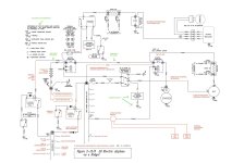
Attached is my modified Z-13 diagram, my knowledge of electrics being quite weak, I would really appreciate any inputs, correction and review of my modification.

RV-10 Z-13 architecture with a single battery, 2 alternators. 2 good old magnetos, no EI. Electrical and avionic redundancy to aim for IFR authorization/operation (quite uncommon and difficult here in Europe). Philosophy is to keep it as simple as possible and goal is to have a failure of the main alternator, main bus, battery contactor covered and to keep for an extended period of time only the necessary instruments to fly the right way up, navigate and shoot an ILS through an independent essential bus.

One question (in green) is about wire size with aft battery, the remark is misleading. Shall I go back to 2AWG ISO 4AWG for the wires in and out of the battery contactor ?

Is the Crowbar OVM module and grounding in the DC Power Master switch necessary (the plane power main alternator has already an overvoltage protection but not sure there is a link between the 2 ?

In general, where should the S704-1 relay be positioned in relation to the switch (doesn’t matter, within 6 inches…)

Thanks in advance and enjoy your day !
 

Attachments

  • Z13 YB V1 MAR23.jpg
    Z13 YB V1 MAR23.jpg
    225.9 KB · Views: 210
Last edited:
2nd alternator

I would look into the Monkworkz secondary alternator. Much simpler install and I think better functionality
 
Aft battery

Most 10 builders are using 2 awg for the aft battery location. The size wire for the contactor is ok as shown as the amperage needed is quite low.

As mentioned, there are now being sold many standby alternators being sold by multiple vendors including B&C who have a new design rated at 35 - 60 amps.
 
Last edited:
Have you done a load analysis? Do you really need a 60 amp main alternator? Doesn’t seem like it from a quick look at what you are planning from your schematic. The B&C 40 amp unit is very reliable. I would also suggest you consider bumping up the capability of your backup alternator.
 
Thanks a lot for your inputs.

The 60amp main alternator is actually the stock one found in the RV-10 Firewall Forward kit, I did not do load analysis for the main bus.

For the essentiel bus (and strictly the items needed for continued flight in IMC) I come out with 5.0 amp typical to 9.8 amp maximal when transmitting, thus my choice for the SD-8. (producing 6.8 amp at 2300RPM).

I agree it's a bit weak but was chosen for its reliability and history more than for its performance. I had the impression a 40 amp backup unit was not necessary specially with a non-electrical dependent engine.

But very open to review and change what needs to be :)
 
Fwiw I have 2x pc680s in my 10 which are locally grounded.
I have 2x 4AWG wires to the cross feed and then starter contactor.
They run right by my feet and exhibit nil temperature rise starting the engine.
 
SNIP
For the essentiel bus (and strictly the items needed for continued flight in IMC) I come out with 5.0 amp typical to 9.8 amp maximal when transmitting, thus my choice for the SD-8. (producing 6.8 amp at 2300RPM).

I agree it's a bit weak but was chosen for its reliability and history more than for its performance. I had the impression a 40 amp backup unit was not necessary specially with a non-electrical dependent engine.

Of the two airplanes at the airpark running an SD-8, both had it fail after a few years in service. One was the sacrificial gear coupler going south, the other I’m not sure about.

If you look at the MonkWorx unit (I’m running that on my RV-8) it has other advantages besides compact size, low weight and good output. The software defined controller does the work of a tradional voltage regulator as well as:
- Over voltage trip
- Integral output fuse
- Integral current shunt (direct input to your EFIS EMS)
- Selectable mode (primary or backup alternator)
- Low current On/Off switch control (I just leave it on as I have it installed as a backup alternator).

On the primary alternator size, LED use of landing lights and such have significantly reduced system current draw. The kicker is what you are using for batteries and you tolerance level of time to restore charge after a hard start. While most of us can easily get by with a 30 or 40 amp primary alternator this consideration leads a larger unit. EarthX options may drive the larger alternator as well. But builder choice to match mission.

Suggestion. Loose the “Avionics Master”. If you must have one then install two for IFR. Each avionics buss feeding half your panel (as in left Avionics buss feeding the left EFIS, Comm #1, etc.).

Carl
 
Voltage drop per ft.

The attached is a good reference for awg wire need, amp max, and voltage drop per run length. 4 awg is the standard for feeding your starter and has been for many years. Many Z drawing reference using 4 awg and should work fine. Although most Z drawings took for granted the batteries where on the firewall. (Make sure you use the total length of the electric path including dedicated return ground runs if used). Not sure what starter you are using but the SkyTech lightweight one (I think called the LS) can be a bit of an amp hog and you don't want much voltage drop with that one especially if you are using a lead acid battery. The Earth X batteries can spin starters with better authority but then you have increased amperage and even higher voltage drops. Good luck with the build, it's a great experience and makes one a better pilot in the end since you know your airframe intimately.
 

Attachments

  • AC43.13-Wire-Gauge-Chart (1).pdf
    139.8 KB · Views: 97
MonkWorx unit
- Over voltage trip
- Integral output fuse
- Integral current shunt (direct input to your EFIS EMS)
- Selectable mode (primary or backup alternator)
- Low current On/Off switch control (I just leave it on as I have it installed as a backup alternator).
Carl

Thanks for the props Carl! it's actually Monkworkz and I also provide:
  • ammeter function through "proportional voltage" that scales from 0-2.7 based on current output much like a hall effect current sensor
  • Active indication that pulls to ground when the device is active, this will run and LED or interface with a Garmin or Dynon contact input to let you know when the regulator is active
 
Thanks a lot for the inputs on wire size and backup alternator, I will look into it.

Anyone for the necessity or not to have the OVM-14 crowbar over voltage module and grounding on the DC power master switch ? It doesn't appear on the Z-12 or Z-14 diagram and I am wondering why it would be needed there...
 
Back
Top