-POSTING RULES

-Advertise in here!
-
Today's Posts
|
Insert Pics
Keep VAF
Going
Donate methods

Point your
camera app here
to donate fast.
|

11-25-2021, 10:37 AM
|
|
|
Join Date: Sep 2010
Location: Houston Texas
Posts: 96
|
|
Magneto /Ignition Switch connection clarification
Good morning folks and happy thanksgiving.
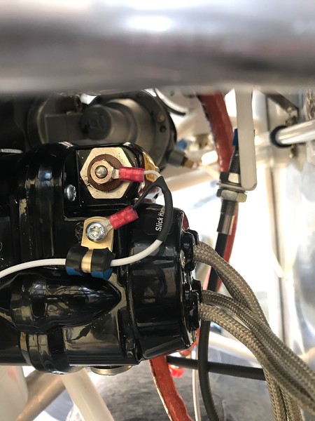
Can you please give me some guidance here. I have my slick mags that i ordered with my lycoming 4 cylinder 0-360 carb engine. From what I have read till now, i will need to connect the p-leads from each slick mag to the R and L tabs on the switch. The switch I have is A-510-2 ignition switch. I also need to use shielded wire. please see questions below:
1) Do I use a 20 ga 1 cable shielded wire for each mag or do I need an 18 ga 1 cable shielded wire? I plan to use the shield as the second wire for grounding
2) Do I need to connect the shield to both ends? that is do I need to connect one end of the shield to the magneto and the other end of the shield to the ground tab on my switch? in effect turning my 1 cable shielded wire to two cable shield wire, one wire connecting to p-lead on mag and switch and the shield wire connecting on mag ground and switch ground.
thank you
|

11-25-2021, 11:06 AM
|
 |
|
|
Join Date: Mar 2006
Posts: 337
|
|
Wiring diagram Z-26 of Bob Nuckolls Aeroelectric Connection has a detailed diagram for wiring the Gerdes A-501-2 switch including wire gauge and how to handle the grounding and the shields. You can download a pdf of the book for free.
Here is a screen grab of the diagram:

__________________
Dave Binkley
RV-6, O-360-A1A, C/S
1932 Monocoupe 110, Warner 145 ( http://gobinkley.com)
Sedona, AZ
|

11-25-2021, 01:16 PM
|
|
|
Join Date: Dec 2011
Location: Livermore, CA
Posts: 8,169
|
|
Above post shows diagram. Yes, shield to proper terminals on both ends, the shield acts as a conductor in this application. You didn’t ask, but also note the jumpers installed on the switch - they need to conform to your type mags (as shown, for left impulse, right non-impulse). Also make sure the wires are supported to minimize flexing, especially at the crimps. I once nearly killed myself after a P lead broke right at the connector.
|

11-25-2021, 02:28 PM
|
|
|
Join Date: Jan 2016
Location: Southwest
Posts: 2,172
|
|
Note
Please note, as I mentioned in another post, the GRD on the switch does not have a connection to the aircraft structure ground. You do not want the aircraft structure ground connected to this circuit. At the magneto, the ground for this wire will be hooked to the engine case ground automatically. This way, the mag shield does not carry any current between the aircraft structure and engine case, only mag current. Just follow the diagram and you will be fine.
__________________
John S
WARNING! Information presented in this post is my opinion. All users of info have sole responsibility for determining accuracy or suitability for their use.
Dues paid 2022, worth every penny
RV9A- Status:
98% done, 2% left to go
Structure done (less gear)
Electrical/Panel done
Firewall Forward 95% done
Fiberglass 70%
www.pilotjohnsrv9.blogspot.com
|

11-25-2021, 06:52 PM
|
 |
|
|
Join Date: Jun 2016
Location: Livermore, CA
Posts: 662
|
|
Quote:
Originally Posted by BobTurner
Above post shows diagram. Yes, shield to proper terminals on both ends, the shield acts as a conductor in this application. You didn’t ask, but also note the jumpers installed on the switch - they need to conform to your type mags (as shown, for left impulse, right non-impulse). Also make sure the wires are supported to minimize flexing, especially at the crimps. I once nearly killed myself after a P lead broke right at the connector.
|
Here's what I think is a pretty nice way to secure the wires on the magneto side. Learned it here on VAF:

|

11-26-2021, 07:27 AM
|
|
|
Join Date: Sep 2010
Location: Houston Texas
Posts: 96
|
|
Thank you Dave. I am using the slick magnito model 4373. No electronic ignition. I think i am clear on the diagram but do not understand the jumper wire. So i install a jumper wire from right terminal to GND terminal? This configuration is for one Non Impulse coupled magneto and one electronic ignition. I am not sure i have this configuration. so question is , do i just follow the diagram as is as far as installing the jumper?
|

11-26-2021, 08:45 AM
|
|
|
Join Date: Oct 2013
Location: Schaumburg, IL
Posts: 7,002
|
|
Quote:
Originally Posted by osaleh
Thank you Dave. I am using the slick magnito model 4373. No electronic ignition. I think i am clear on the diagram but do not understand the jumper wire. So i install a jumper wire from right terminal to GND terminal? This configuration is for one Non Impulse coupled magneto and one electronic ignition. I am not sure i have this configuration. so question is , do i just follow the diagram as is as far as installing the jumper?
|
If wired according to the above diagram, the switch will only allow the left mag to fire with the key in the S position. It is critical that you use the specific grd posts shown.
__________________
N64LR - RV-6A / IO-320, Flying as of 8/2015
N11LR - RV-10, Flying as of 12/2019
|

11-26-2021, 09:11 AM
|
 |
|
|
Join Date: Oct 2005
Location: 08A
Posts: 10,707
|
|
Quote:
Originally Posted by BobTurner
Also make sure the wires are supported to minimize flexing, especially at the crimps. I once nearly killed myself after a P lead broke right at the connector.
|
Yes please, and me too. Classic case...A-65 Continental, somebody moved the prop just a little, the impulse clicked, and thankfully the three or four revs missed all the guys clustered around the nose.
.
__________________
Dan Horton
RV-8 SS
Barrett IO-390
|

11-26-2021, 12:47 PM
|
|
|
Join Date: Dec 2011
Location: Livermore, CA
Posts: 8,169
|
|
Quote:
Originally Posted by osaleh
Thank you Dave. I am using the slick magnito model 4373. No electronic ignition. I think i am clear on the diagram but do not understand the jumper wire. So i install a jumper wire from right terminal to GND terminal? This configuration is for one Non Impulse coupled magneto and one electronic ignition. I am not sure i have this configuration. so question is , do i just follow the diagram as is as far as installing the jumper?
|
The diagram shows the connections when using an impulse mag on the left, and a non-impulse mag on the right. The jumper disables the right mag on starting. If you are using two impulse mags (as it appears you are) then you want both enabled for start - no jumpers.
|

11-27-2021, 05:14 PM
|
|
|
Join Date: Sep 2010
Location: Houston Texas
Posts: 96
|
|
Thank you all folks . Inquiry cleared . It seems I have the same magnetos as diagram so will follow that .
|
Thread Tools |
Search this Thread |
|
|
Display Modes |
Linear Mode
|
Posting Rules
|
You may not post new threads
You may not post replies
You may not post attachments
You may not edit your posts
HTML code is Off
|
|
|
All times are GMT -6. The time now is 12:02 PM.
|