What's new
Van's Air Force

Don't miss anything! Register now for full access to the definitive RV support community.

Photo request: firewall layouts

N546RV

Well Known Member
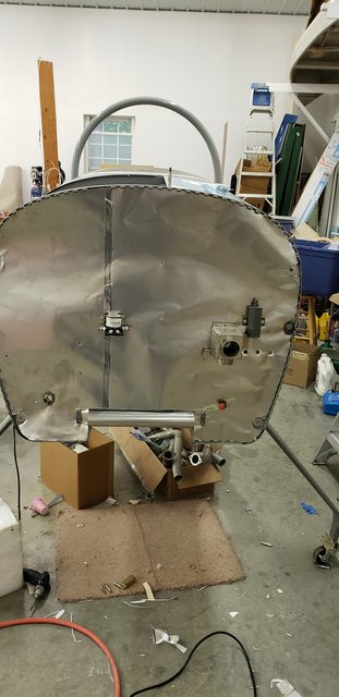
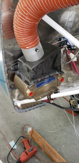
OK, I am seriously tying myself into knots trying to mentally juggle all the decisions required for laying out my engine compartment, particularly the items mounted to the firewall and the penetrations for wiring. I would greatly appreciate any photos anyone can provide of how their firewall ended up.

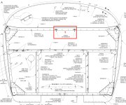
And on a similar note - I can't for the life of me figure out the purpose of the two nutplates near the center of the upper firewall angle. (see attachment) From the FWF photos I've managed to run across - such as Mickey's great set here don't seem to show anything attached there, though it's hard to tell. Can anyone shed light on this?

Signed, a builder experiencing all the challenges of systems planning. :)
 

Attachments

  • Screen Shot 2020-10-05 at 11.04.01 PM.jpg
    Screen Shot 2020-10-05 at 11.04.01 PM.jpg
    334.3 KB · Views: 515
nutplates

IIRC the RV-8 plans don't give you all the exact locations of things like the battery box, contactors, oil/fuel pressure manifold, brake fluid reservoir, etc.

If you are not sure where you will place those things, which is totally normal at your stage of the build, don't worry about it. You can add them later. I'd avoid putting those nutplates in now, just either put the rivet in, or leave it open for later. Drilling out the rivet and adding a nutplate later is easy. It's also easy to get a nut in place like that, so a nutplate is not really needed.

I recommend punching or cutting the huge holes in the stainless steel as early as possible, when you have easier access to the FW. They are not that easy to cut, but if you get a good hole punch it's easier, I've been told. I did it the hard and painful way - with a hole saw, lots of oil, with a very slow drill. Then cleaned up with a dremel.

I have a lot of useless holes in my FW that I needed to patch because I started my build with a Subaru and then switched to a Lycoming, so if you see a screw or a bolt somewhere that does not make sense, that's probably why.
 
Those nutplates are for adel clamps to support the oil pressure hose. Its shown on the OP35 Drawing


Here's my FW layout. My battery is in the back.

Most of the wires come through two holes in the lower LH side except for the EGT and CHT wires for the RH side of the engine and the two mag wires. Those come through a hole in the RH side center.


Last edited:
I purchased the Firewall Forward Kit and it came with a bunch of drawings not available in the original RV8 preview. These drawings will show the various firewall layouts for fuel injected and carburated engines and I think they will help you to visualize the possible firewall layouts of your engine. They include the various oil lines, fuel lines, fuel vents and other stuff related to the firewall forward installation. I also went to the airport and took a bunch of pictures from another RV8A to use as reference in addition to the other pictures posted in the forum.

I am almost at the FF installation stage as Lkitson. I am waiting to get the rear canopy installed before returning to the FF again.
 
Last edited:
The OP drawings provide the details for various engine and prop types, etc.
These are all in the preview plans CD/USB.
For instance, OP-35 give the details for the firewall layout for an O-320/360.

(Those two nutplates are for Adel clamps for the oil pressure hose.)
 
Phillip,

Recommend you first make some big decisions:
- Battery mounted on the firewall or not?
- Oil cooler mounted on the baffle or firewall?

From this everything else falls out.

I found one photo of the firewall during the Fiberfrax and 0.005” SS clad installation. The second photo is how I mounted the oil cooler.

One wire penetration under the oil cooler and one outboard of the brake reservoir.

I prefer firewall mounted oil coolers and batteries not mounted in the engine compartment. I have one PC-625 in the forward baggage well and one PC-625 in the standard aft location. This worked very well for my W&B.

Carl
Just rolled 100 hours on the new RV-8
C7-FE3-E19-7-C0-E-456-C-81-E2-E4-A5-E284-F7-EF.jpg

E15-A3180-7222-4178-B72-F-64811-C46-A816.jpg
 
Those nutplates are for adel clamps to support the oil pressure hose. Its shown on the OP35 Drawing


Here's my FW layout. My battery is in the back.

Most of the wires come through two holes in the lower LH side except for the EGT and CHT wires for the RH side of the engine and the two mag wires. Those come through a hole in the RH side center.


Nice layout Lkitson, what brand/part number are your four electrical firewall passthroughs? Thanks
 
The OP drawings provide the details for various engine and prop types, etc.
These are all in the preview plans CD/USB.
For instance, OP-35 give the details for the firewall layout for an O-320/360.

(Those two nutplates are for Adel clamps for the oil pressure hose.)

Thank you, this is a godsend...it never occurred to me to look in the OP drawings folder.
 
A few things to consider...
* Make as many things accessible as possible without having to remove the bottom cowling. The -8 bottom cowl will be lots easier to remove than the -9A bottom cowl so that gives you an advantage
* On my -9A, the MP readout is sluggish and I think this is because the line from firewall sensor to manifold is too long. I wish that my sensor was on the right side of the firewall, not the left
* Make the brake master cylinder accessible
* Do what you can so that you don't make a mess changing the oil filter. Remote mount is one way but my plane doesn't have it. We always make a mess. Lots of obstructions back there
* Permanently installed are wires for a "Genius" trickle charger. It can and has resuscitated a dead battery, paying for itself
 
Back
Top